There are a few options out there for getting analogue audio data into the ESP32.
- Directly reading from the built-in Analogue to Digital Converts (ADCs)
- This is useful for one-off readings, but not suitable for high sampling rates.
- Using I2S to read from the built-in ADCs using DMA
- Useful for analogue microphones such as the MAX4466 and the MAX9814
- Using I2S to read directly from I2S compatible peripherals
- Useful for microphones such as the SPH0645LM4H, INPM441, ICS43432 and ICS43434
I’ve covered these options in a couple of YouTube videos which are worth a watch and I’ve added details in the text below as well if videos aren’t your thing.
There’s also a GitHub repo with all the necessary code here.
Analogue Microphone input (MAX4466 and MAX9814)
Digital Microphone input (SPH0645LM4H, INPM441)
Reading from the ADC directly
There are two built-in ADCs on the ESP32, ADC1 and ADC2.
ADC1 has 8 channels:
| Channel | GPIO | Channel | GPIO |
|---|---|---|---|
| ADC1_CHANNEL_0 | GPIO36 | ADC1_CHANNEL_4 | GPIO32 |
| ADC1_CHANNEL_1 | GPIO37 | ADC1_CHANNEL_5 | GPIO33 |
| ADC1_CHANNEL_2 | GPIO38 | ADC1_CHANNEL_6 | GPIO34 |
| ADC1_CHANNEL_3 | GPIO39 | ADC1_CHANNEL_7 | GPIO35 |
And ADC2 has 10 channels:
| Channel | GPIO | Channel | GPIO |
|---|---|---|---|
| ADC2_CHANNEL_0 | GPIO4 | ADC2_CHANNEL_5 | GPIO12 |
| ADC2_CHANNEL_1 | GPIO0 | ADC2_CHANNEL_6 | GPIO14 |
| ADC2_CHANNEL_2 | GPIO2 | ADC2_CHANNEL_7 | GPIO27 |
| ADC2_CHANNEL_3 | GPIO15 | ADC2_CHANNEL_8 | GPIO25 |
| ADC2_CHANNEL_4 | GPIO13 | ADC2_CHANNEL_9 | GPIO26 |
There are some limitations though - ADC2 is also used by the WiFi sub-system and some of the pins are also used strapping pins that control boot behaviour. This means it’s safest to stick with ADC1 for projects.
Reading from the ADC is very straightforward - you can either use the Arduino functions or use the Espressif function directly:
// read using Arduino
int sample = analogRead(35)

// read using Espressif
int sample = adc1_get_raw(ADC1_CHANNEL_7);
The ESP32 ADC is quite inaccurate and if you want to have an accurate reading you can use calibration settings. These are now mostly done at the factory so your ESP32 should already have some calibration settings already. It’s also possible to manually calibrate the ADC but this is not for the faint hearted.
To read a calibrated value you use the following code which will give you a value in millivolts. The two calls to adc1_config_width and adc1_config_channel_atten are critical as the calibration characteristics needs to match the ADC configuration.
// calibration values for the adc
#define DEFAULT_VREF 1100
esp_adc_cal_characteristics_t *adc_chars;

//Range 0-4096
adc1_config_width(ADC_WIDTH_BIT_12);

// full voltage range
adc1_config_channel_atten(ADC1_CHANNEL_7, ADC_ATTEN_DB_11);

// get the ADC characteristics
esp_adc_cal_characterize(
  ADC_UNIT_1,
  ADC_ATTEN_DB_11,
  ADC_WIDTH_BIT_12,
  DEFAULT_VREF,
  adc_chars);

// read a sample from the ADC
int sample = adc1_get_raw(ADC1_CHANNEL_7);

// get the calibrated value
int milliVolts = esp_adc_cal_raw_to_voltage(sample, adc_chars);
High-Speed ADC Sampling Using I2S and DMA
Using the ADC directly is fine for low frequency and one-off sampling. For sampling high-quality audio data you will need to be sampling at 16-40KHz (watch the first video for some nice animation on this!). You can do this using a timer, but it’s not the best use of the ESP32’s CPU resources.
A better approach is to use the built-in I2S peripheral to read samples from the ADC directly into memory.
This is the basic setup for using I2S to read from the built-in ADC.
i2s_config_t i2s_config = {
    .mode = (i2s_mode_t)(I2S_MODE_MASTER | I2S_MODE_RX | I2S_MODE_ADC_BUILT_IN),
    .sample_rate = 40000,
    .bits_per_sample = I2S_BITS_PER_SAMPLE_16BIT,
    .channel_format = I2S_CHANNEL_FMT_ONLY_LEFT,
    .communication_format = I2S_COMM_FORMAT_I2S_LSB,
    .intr_alloc_flags = ESP_INTR_FLAG_LEVEL1,
    .dma_buf_count = 2,
    .dma_buf_len = 1024,
    .use_apll = false,
    .tx_desc_auto_clear = false,
    .fixed_mclk = 0};

//install and start i2s driver
i2s_driver_install(I2S_NUM_0, &i2s_config, 4, &i2s_queue);

//init ADC pad
i2s_set_adc_mode(ADC_UNIT_1, ADC1_CHANNEL_7);

// enable the ADC
i2s_adc_enable(I2S_NUM_0);

// start a task to read samples from I2S
TaskHandle_t readerTaskHandle;
xTaskCreatePinnedToCore(readerTask, "Reader Task", 8192, this, 1, &readerTaskHandle, 0);
You can then read samples from the ADC using the following task:
void readerTask(void *param)
{
    I2SSampler *sampler = (I2SSampler *)param;
    while (true)
    {
        // wait for some data to arrive on the queue
        i2s_event_t evt;
        if (xQueueReceive(sampler->i2s_queue, &evt, portMAX_DELAY) == pdPASS)
        {
            if (evt.type == I2S_EVENT_RX_DONE)
            {
                size_t bytesRead = 0;
                do
                {
                    // try and fill up our audio buffer
                    size_t bytesToRead = (ADC_SAMPLES_COUNT - sampler->audioBufferPos) * 2;
                    void *bufferPosition = (void *)(sampler->currentAudioBuffer + sampler->audioBufferPos);
                    // read from i2s
                    i2s_read(I2S_NUM_0, bufferPosition, bytesToRead, &bytesRead, 10 / portTICK_PERIOD_MS);
                    sampler->audioBufferPos += bytesRead / 2;
                    if (sampler->audioBufferPos == ADC_SAMPLES_COUNT)
                    {
                        // do something with the sample - e.g. notify another task to do some processing
                   }
                } while (bytesRead > 0);
            }
        }
    }
}
Once you’ve read the samples you can do whatever processing you need to do, the I2S peripheral will continue in the background reading samples from the ADC into the DMA buffers.
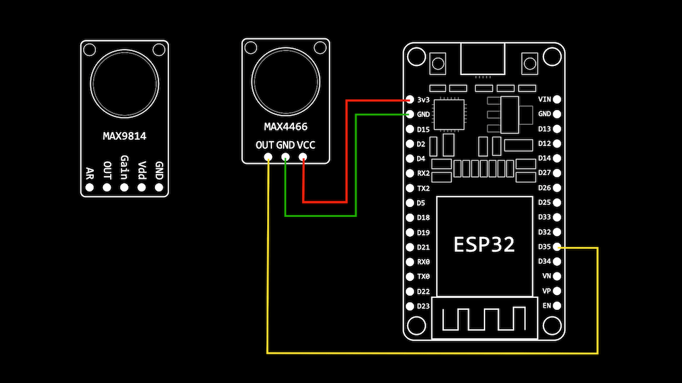
Wiring up the MA4466 is very straightforward, you just need to connect VCC to 3v3, GND to GND and Out to the GPIO pin that corresponds to the ADC channel you are sampling from.
The same is try of the MAX9814 - you can also play with the gain on the MAX9814 by connecting the Gain pin to either VCC or GND.
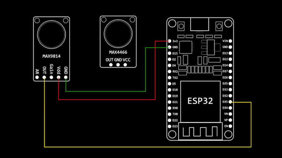
My testing of both these boards highlighted an issue with noise coming from the 3v3 line (you can listen to the audio in the first video). We can easily see this by hooking up an oscilloscope on the 3v3 line and the microphone output.
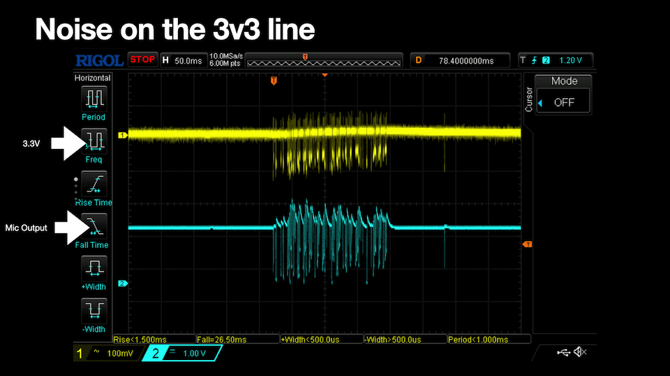
This noise on the 3v3 line is also apparent on the 5v rail but we can generate a reasonably clean signal by filtering the 5v volt line and feeding it through a low dropout regulator.
For very low current draw like these microphone boards, we can have a simple RC filter on the 5v rail.
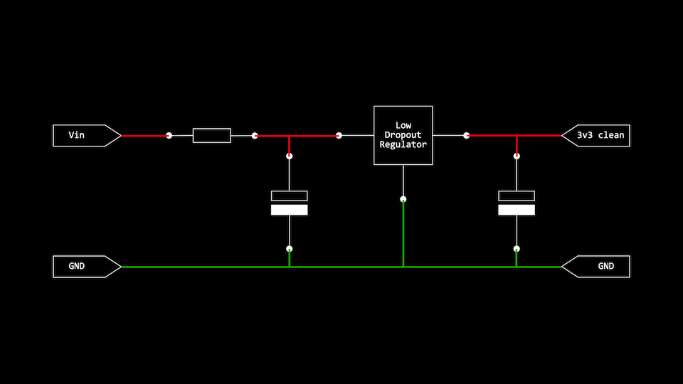
I’ve gone slightly further and made up a more complex circuit with multiple filters, which I’ve also had made up into a circuit board, but this is not necessary.
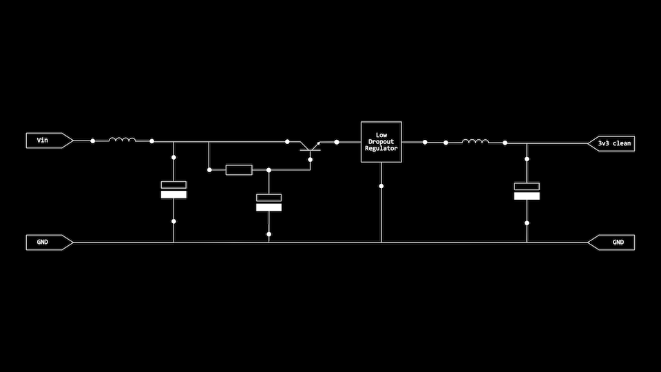
With either the simple filter or the more complex filter we get reasonably audio, but it is still quite noisy.
You can listen to the audio of the two boards at this point of the video:
I2S microphones
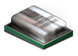
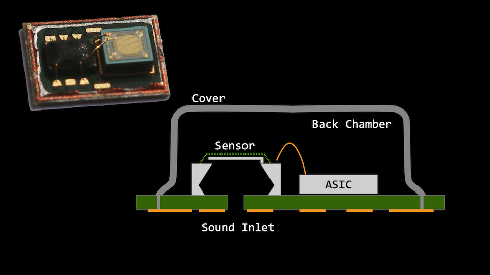
I’ve also tried out two MEMS (Micro-Electro-Mechanical Systems) microphones that have built-in I2S interfaces. I’ve got an INMP441 and an SPH0645LM4H for my experiments.
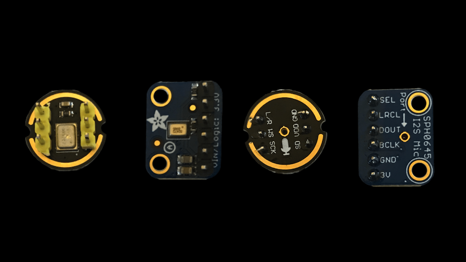
These are tiny microphone modules that are packages up as tiny surface-mounted components. Typically they will have a hole in the bottom through the circuit board or in the top of the package. Both the boards that I have are bottom ported so there is a hole in the circuit board for the audio to enter the system.
Once again the wiring up of these modules is very simple - we just need three GPIO pins.
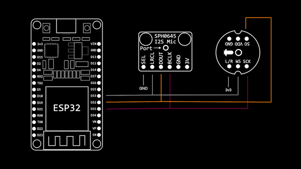
The three required lines are:
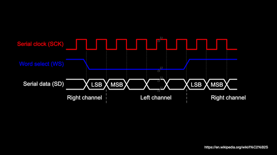
- Serial Clock - this is used to clock data to or from the peripheral
- Word select (also called the left-right clock or LRCLK) - this selects the channel that you want to send or receive data for.
- Serial Data - the data that is being either transmitted or received
The word select should in theory let us connect two different devices - one for the left channel and one for the right channel.
When the Word Select is low the right device with tri-state its output and the left channel will sever data. when the word select is high the left device will tri-state its output and the right device will server data.
We can set up the I2S interface to read directly from these two microphones by configuring each board to be on a different channel.
The configuration for the I2S interface now looks like this:
i2s_config_t i2s_config = {
    .mode = (i2s_mode_t)(I2S_MODE_MASTER | I2S_MODE_RX),
    .sample_rate = 40000,
    .bits_per_sample = I2S_BITS_PER_SAMPLE_32BIT,
    .channel_format = I2S_CHANNEL_FMT_RIGHT_LEFT,
    .communication_format = I2S_COMM_FORMAT_I2S,
    .intr_alloc_flags = ESP_INTR_FLAG_LEVEL1,
    .dma_buf_count = 4,
    .dma_buf_len = 1024,
    .use_apll = false,
    .tx_desc_auto_clear = false,
    .fixed_mclk = 0};
I had read some forum posts on the SPH0645 that indicated there were some issues with this microphone and ESP32 and when we pull data back with just the SPH0645 plugged in we can see some issues:
| Right | Left | Right | Left |
|---|---|---|---|
| 01 00 00 00 | 00 80 d2 f6 | 01 00 00 00 | 00 00 d1 f6 |
| 01 00 00 00 | 00 00 cc f6 | 01 00 00 00 | 00 00 ca f6 |
| 01 00 00 00 | 00 80 ca f6 | 01 00 00 00 | 00 00 c9 f6 |
| 01 00 00 00 | 00 00 c7 f6 | 01 00 00 00 | 00 80 c4 f6 |
| 01 00 00 00 | 00 80 c3 f6 | 01 00 00 00 | 00 80 c2 f6 |
We have some data in the Right channel even though I configured the SPH0645 to be on the left channel.
Apparently there are some timing changes required to make the SPH0645 work with the ESP32. The magic incantation to make it work properly is:
#include "soc/i2s_reg.h"

// FIXES for SPH0645
REG_SET_BIT(I2S_TIMING_REG(I2S_PORT), BIT(9));
REG_SET_BIT(I2S_CONF_REG(I2S_PORT), I2S_RX_MSB_SHIFT);
With this in place, we can record from both the SPH0645 and the INMP441 at the same time. You can watch a segment of the video here to listen to the audio recordings from the boards:
Conclusion and thoughts
After playing the four boards - the MAX4466, MAX9814, SPH0645 and the INMP441 - I would choose the INMP441 for my projects. If you can get hold of a break out board then the ICS4343 would be an even better option.
- If you are short of GPIO pins then the MX9814 may be a good option
- POSITIVE - it only needs one GPIO pin
- POSITIVE - it has a built-in Automatic Gain Control (AGB).
- NEGATIVE - it’s quite noisy
- NEGATIVE - you will need a good clean power supply
- If you can spare 3 GPIO pins then the INMP441 should be your choice
- POSITIVE - much less noisy than the analog boards
- POSITIVE - no need to power supply filter, handles the noisy power line without any issues
- POSITIVE - very compact and small
- NEGATIVE - no Automatic Gain Control (AGB)
- NEGATIVE - no longer in production - replaced by the ICS4343 which doesn’t have a large supply of break out boards at the moment.