I thought it might be fun to make a USB cable tester. Turns out this was a surprisingly difficult project!
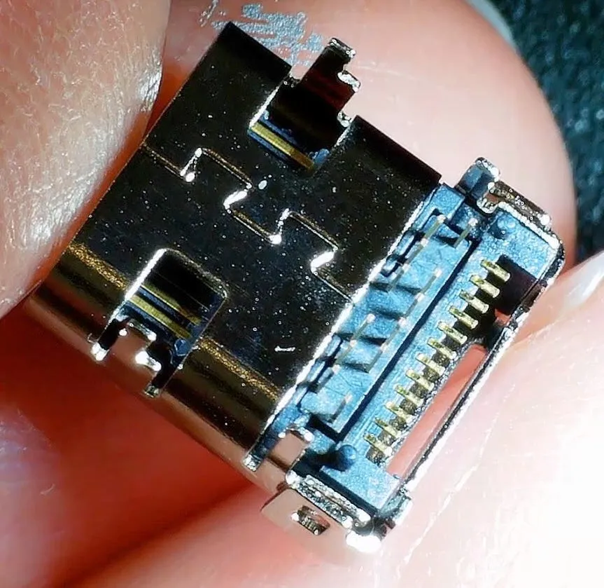
For the first version I used these USB sockets.
These break out all the pins - but unfortunately half the pins are hidden under the socket so you can’t see if you have solder bridges or bad connections. That coupled with a couple of design errors made the first version of the board a bit of a failure.
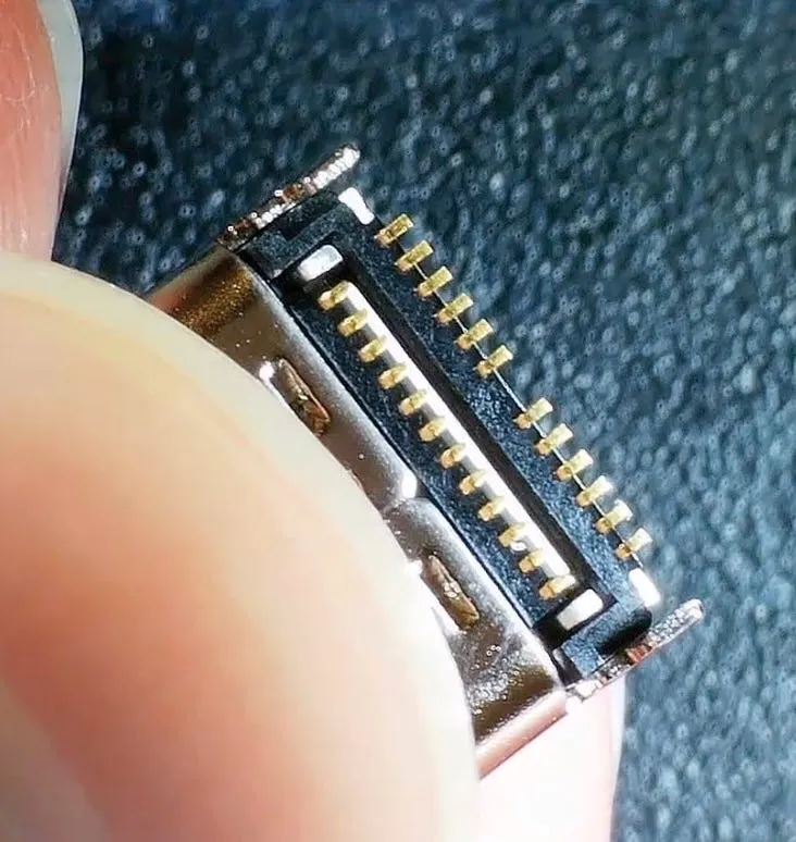
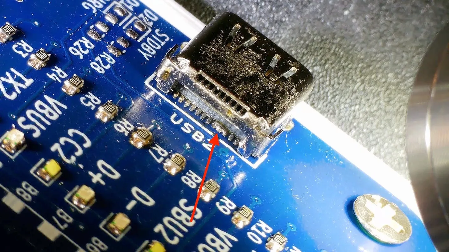
So for version 2 I opted to use these sockets:
These are a lot easier to inspect. Half the pins a through hole and the other half are visible at the back of the socket.
It is still pretty hard to solder up and not get any bridges, but at least now we can see them easily.
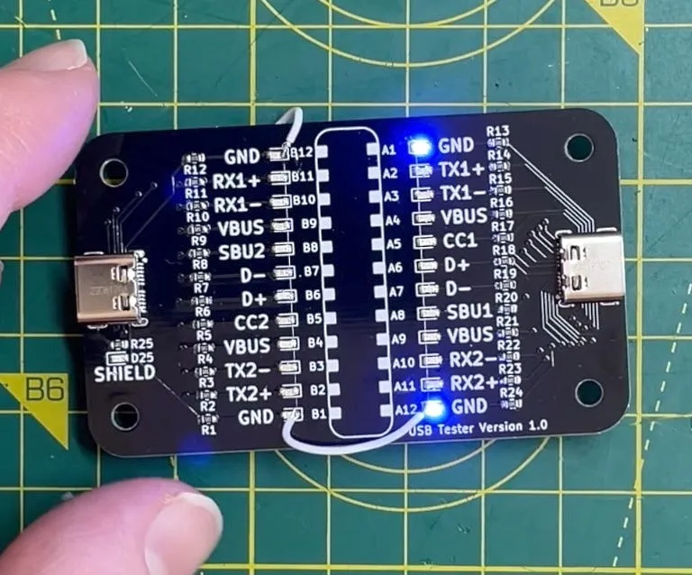
Version 2 works pretty well, we can test various cables - for example here’s a good quality cable that should be able to for 40Gbps.
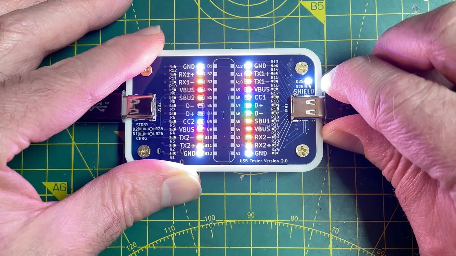
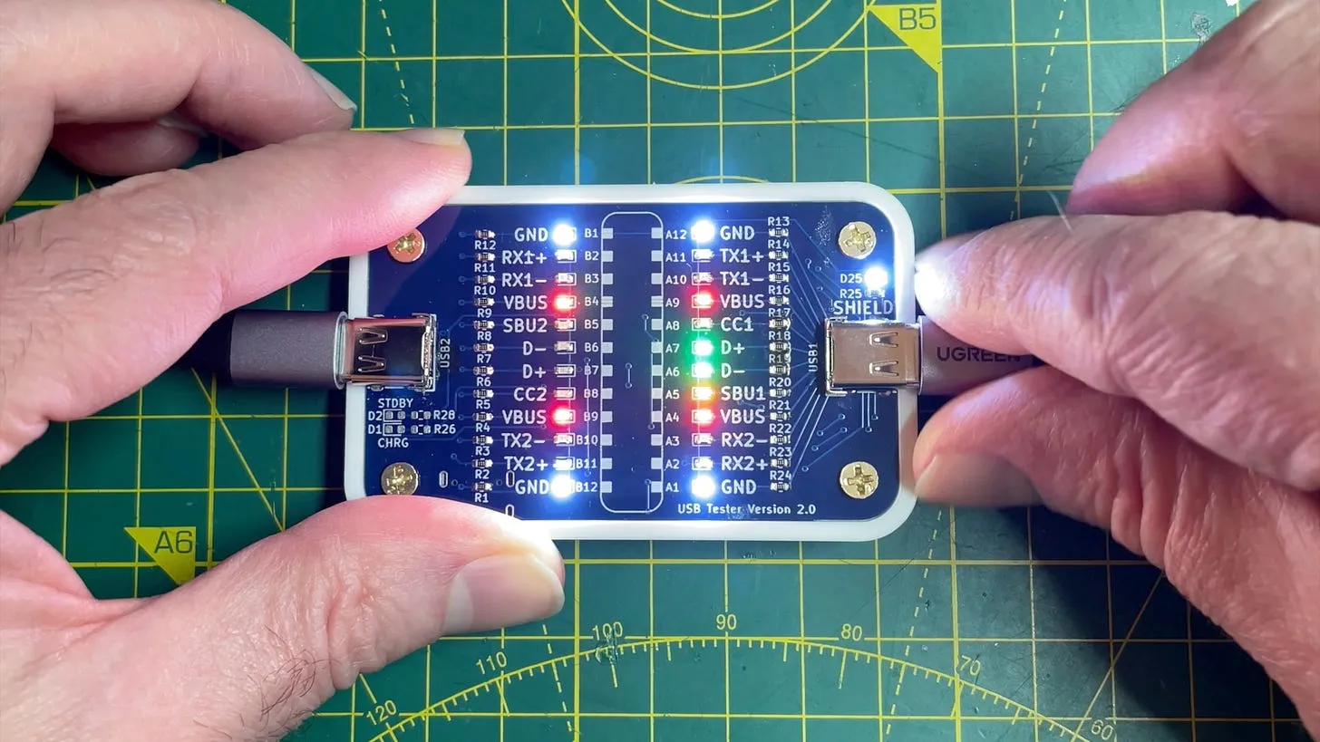
And here’s a cable that is ok for normal USB - but it’s not going to set the world on fire when it comes to speed.
I’ve got a new version under construction. With the previous two versions it’s been really hard to tell if the sockets are soldered on properly. So I’ve now broken out all the connections and can easily build a test jig to check for shorts.
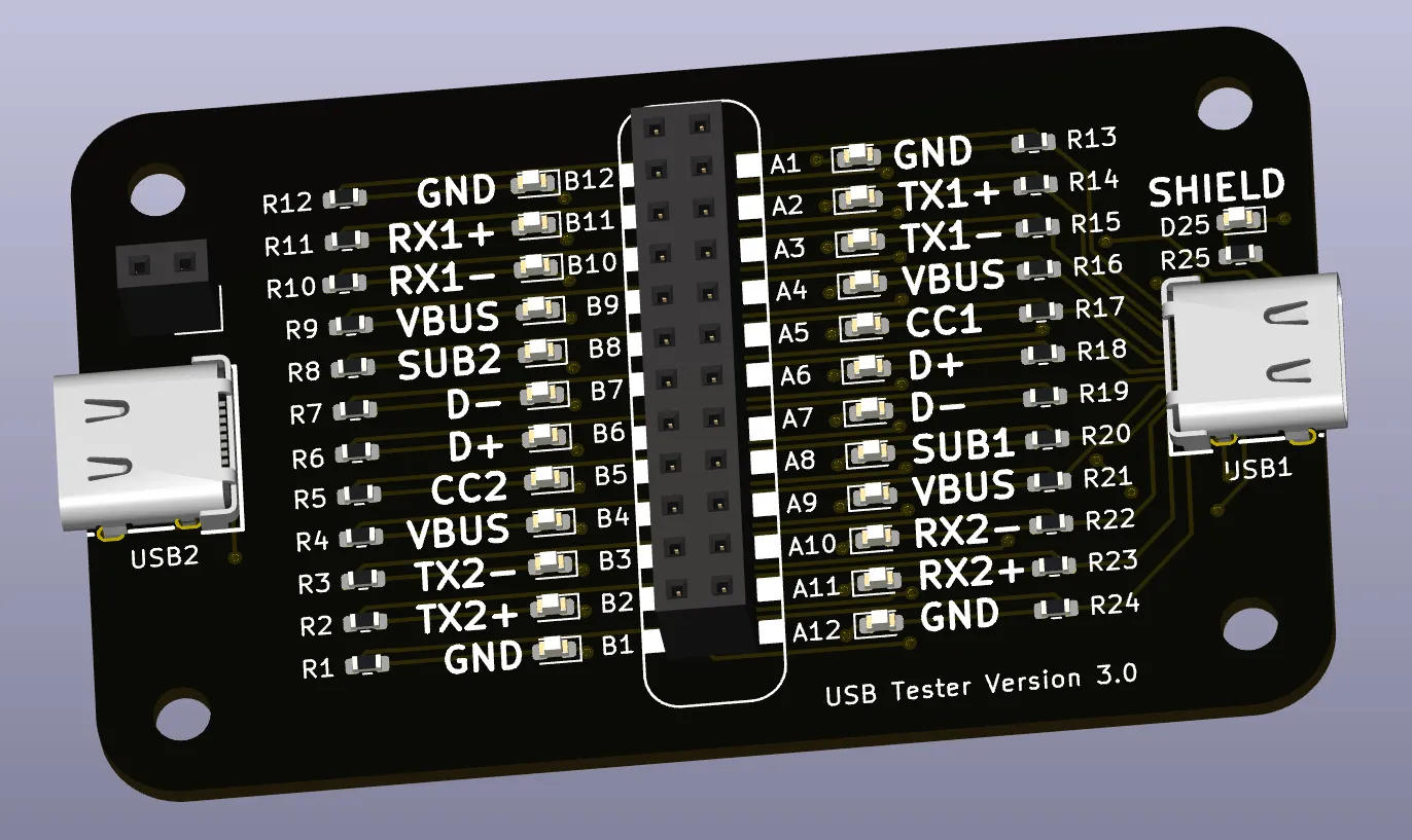
So, keep an eye out for Version 3.0!
How Good Are My USB Cables? - In this video, I engage in a deeper exploration of USB testing, encountering a range of trials and tribulations along the way. First up, I attempt to test a couple of USB cables and discuss their data lines' peculiar situatedness. Then, I delve into the assembly of the PCB boards, sourced from PCBWay, which surely turned into a learning voyage than an easy sail. The first version faced challenges of misordered large-frame stencil, unseen connection problems, and even DRC errors in the submission process. Not dwell on that, I redesign and bring to table Version 2, complete with USB connectors with broken-out pins and designed for visual inspection ease. Although this version demonstrated success, soldering difficulties and bad connections persisted. Considering all the hurdles, I decide to let PCBWay handle the assembly for the next version. For future strategies, adding test points and eliminating the lithium-ion charging circuit seemed more practically viable. Peeping into version 3, testing points for all USB cable pins have been added and even an option to break out actual USB connections, all towards ensuring an improved error checking and usefulness of the assembly.
Easy 8.8 Amp Power Supply Hook Up - But is it safe? - In this DIY assembly venture, I decided to tackle the challenge of designing a safer casing for the bare, open mains connections on my LRS-200-24 power supply. To add to the challenge, the connector size was surprisingly wide and deep, which created hurdles in 3D printing the perfect box. I tried several renditions, from printing in separate parts to changing the design into a tubular construction, but these ventures resulted in a bit of a printing scrap heap. After discovering a sturdy, push-fit, slimmer connector online, my 3D printing journey went a little smoother, resulting in a front panel that slid nicely onto the power supply unit. The project also involved some dexterous wire threading, soldering, securing switches, and sockets, and accommodating everything within the newly printed enclosure. An exciting yet fiddly bit of work, it has come along quite promisingly – a test run confirms functionality. On the agenda for the next round – possibly extending the enclosure for some more elbow room for the wires. Definitely been a 'shocking' fun electrical endeavour!