Danger danger high voltage
read
HELP SUPPORT MY WORK: If you're feeling flush then please stop by Patreon Or you can make a one off donation via ko-fi
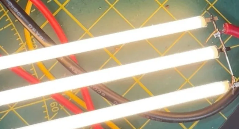
If you’ve been following along (either on the newsletter or the YouTube channel) you’ll know we’ve been experimenting with high-voltage circuits to drive these LED filaments I salvaged from some broken light bulbs.

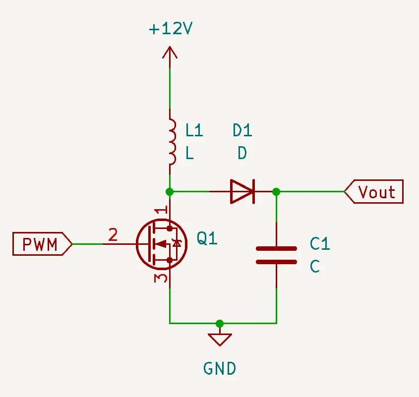
The circuit is pretty simple: it uses a MOSFET, an inductor, a diode, and a smoothing capacitor. We’re switching the inductor on and off at a high frequency using a PWM signal and we can vary the pulse width to change the voltage level.

These filaments start to light up at around 90 volts, and we can go up to about 95–96 volts for a fairly bright output. My meter only starts registering current above 20 milliamps, so it doesn’t pick up the lower values.

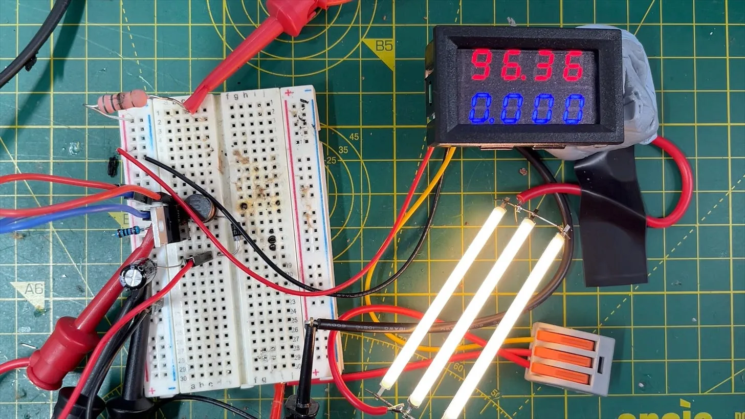
The circuit works quite well, but has no safety features - there’s no over voltage or over current limiting on either the output, or the input. So it’s tends to blow itself up quite readily.
Here’s the remains of a capacitor that blew up. It was rated for 100 volts and it really didn’t like gong higher than that…

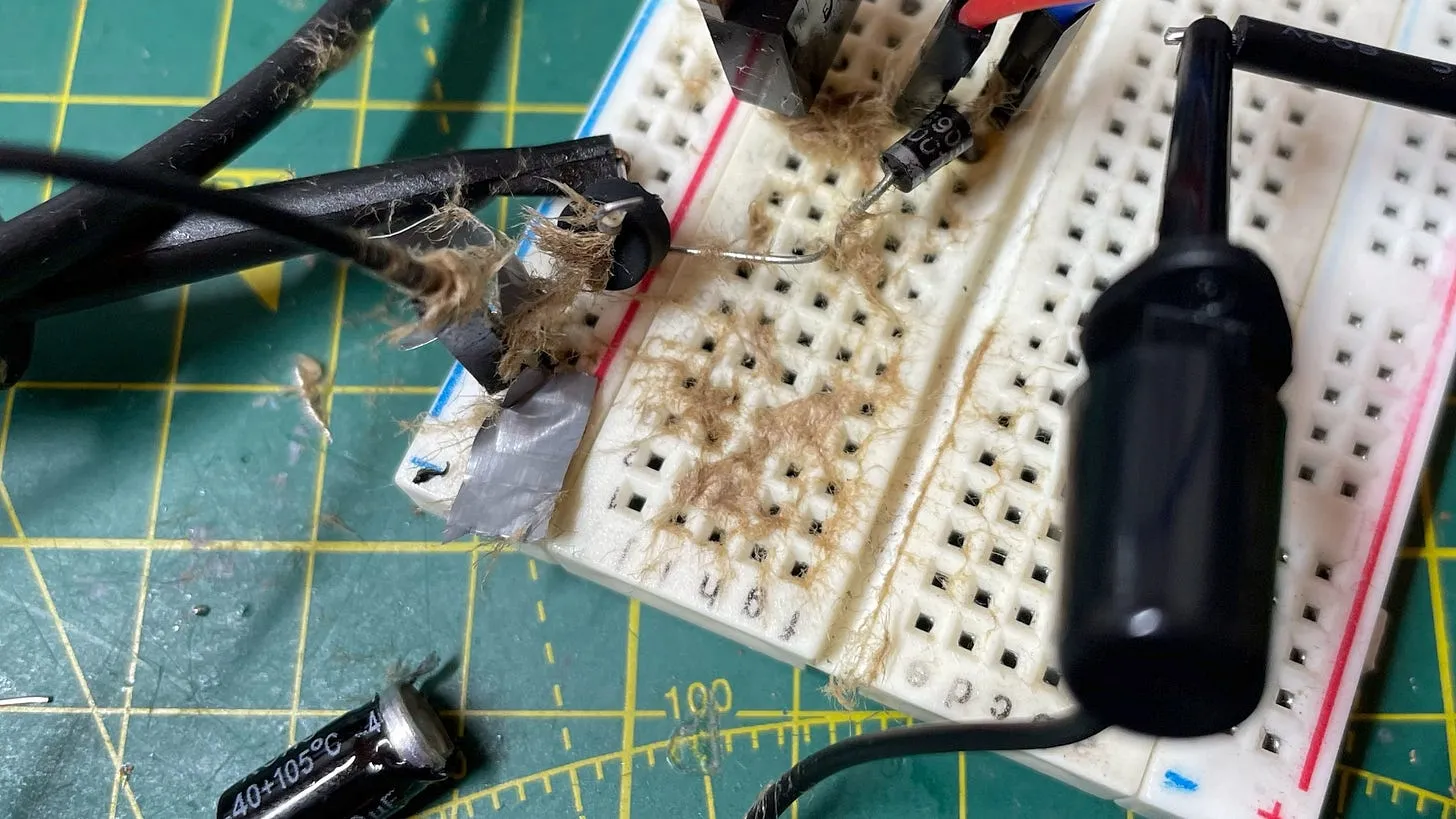
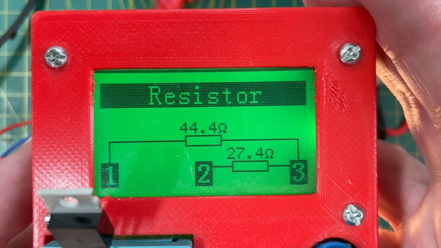
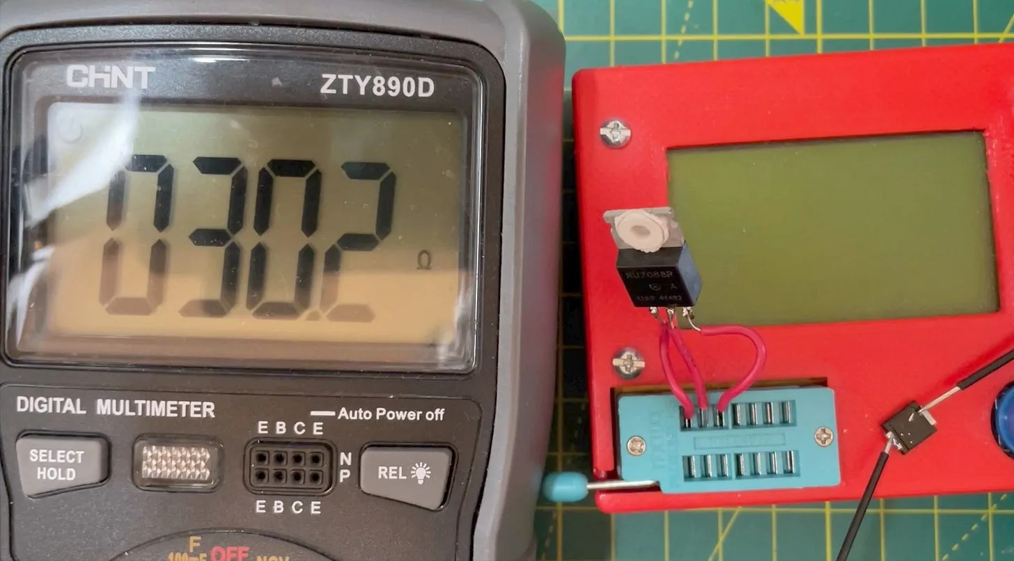
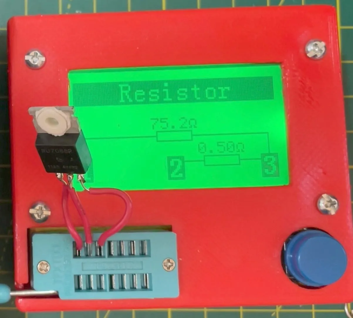
I’m not sure if the failure was due to the diode or the MOSFET, because I’ve had issues with both. Here’s a failed MOSFET—it’s now acting like a resistor divider, which is not ideal.

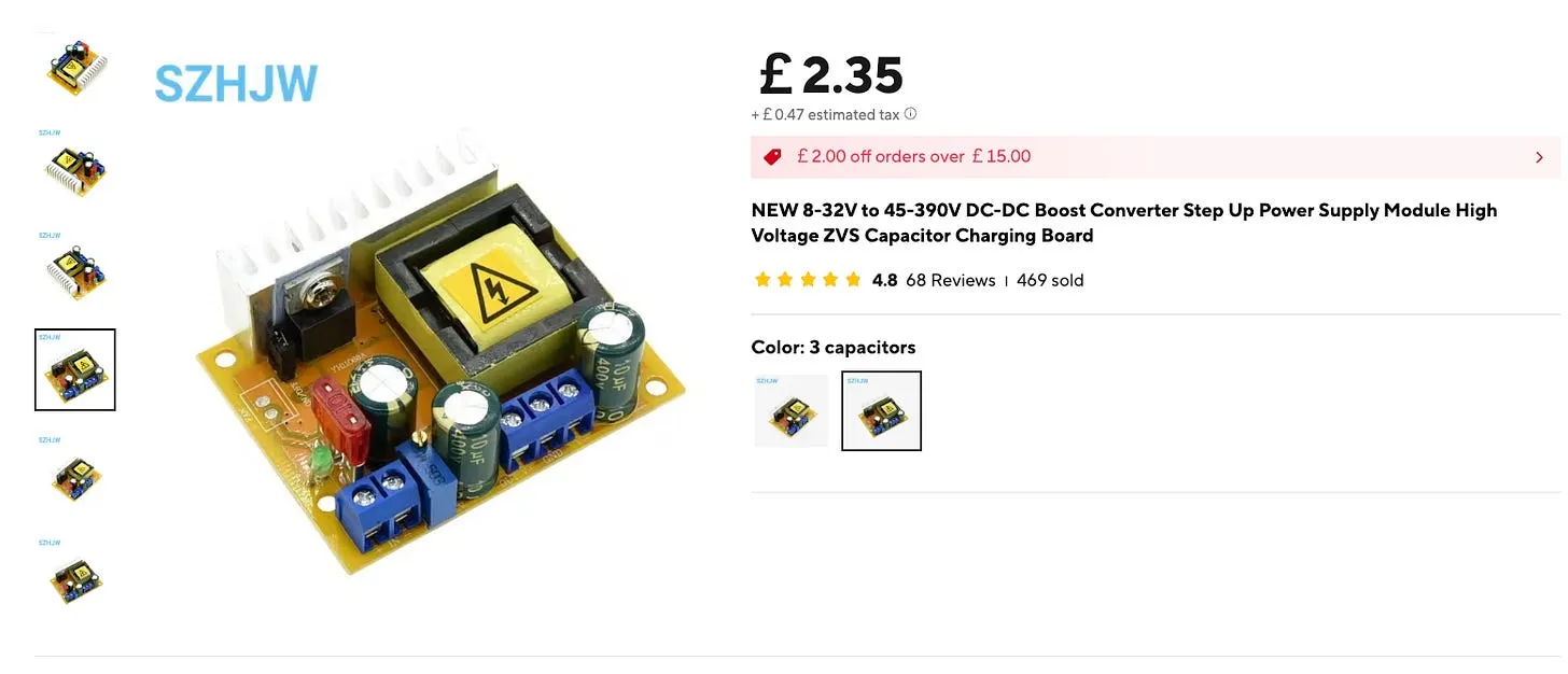
So, I decided to invest in a proper DC-DC converter. I picked up this one, which can output anywhere from 45 to 390 volts. If you use both positive and negative rails, in theory, you can get up to 800 volts.

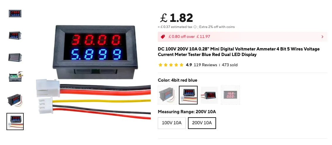
I also picked up a nice meter that can measure up to 200 volts and also does current.

Unfortunately, this one’s dead. It was working at first, though it made a strange clicking noise—and then just failed. Now the input is shorted.

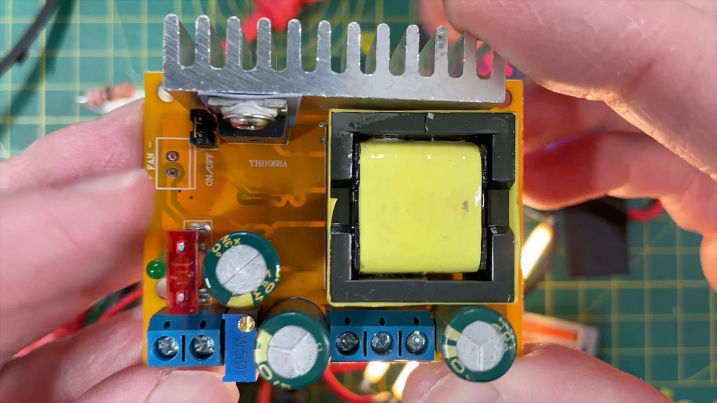
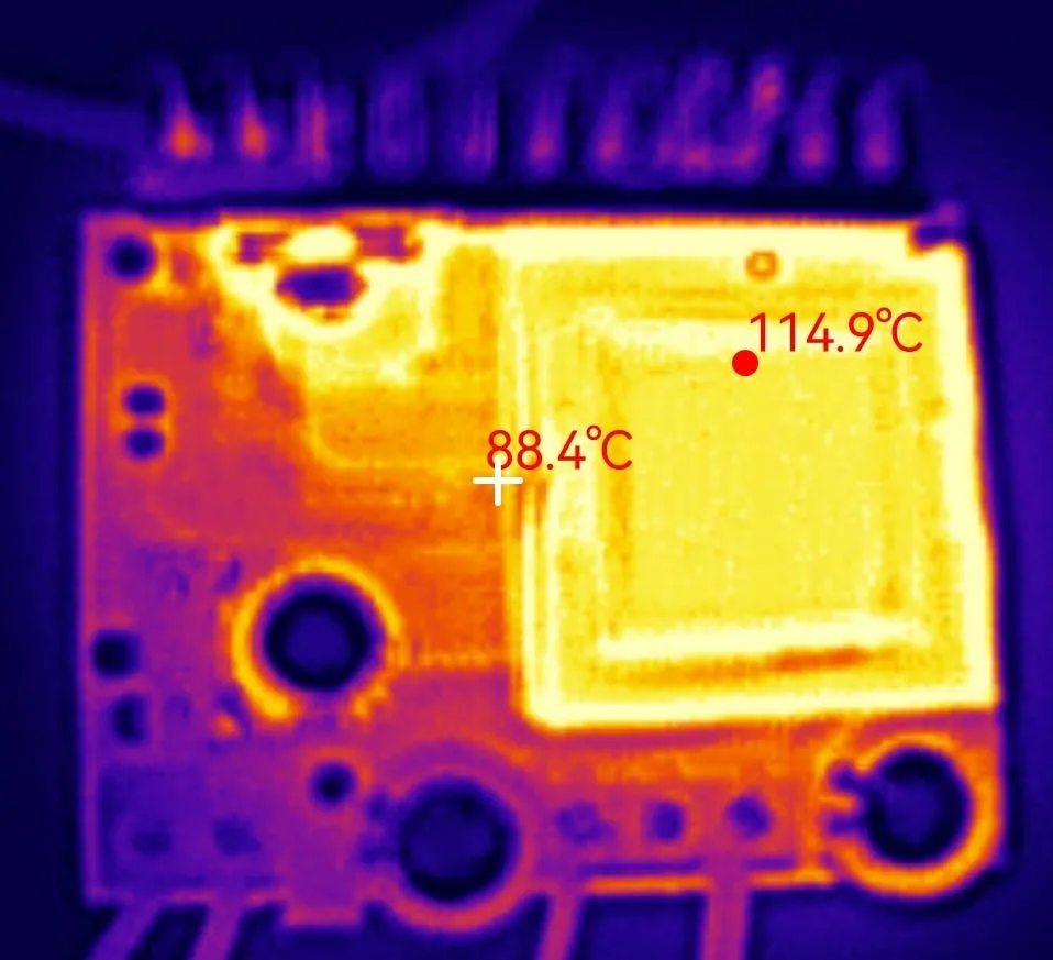
This particular DC-DC converter board can get quite hot. I’ve seen other people mention that it can get too hot to touch. There is a connector for a fan, which I might have to use - if I can get a board that actually works!

Looking at this board, it’s… rough. My soldering isn’t perfect, but this definitely isn’t great.

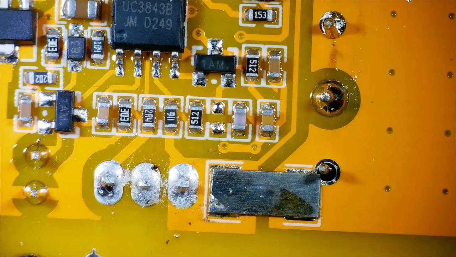
After cleaning it up with a bit of 99% pure alcohol - nothing seems to be particularly wrong - yes the soldering is not great - but it all looks to be connected ok.
I have managed to find a schematic online:

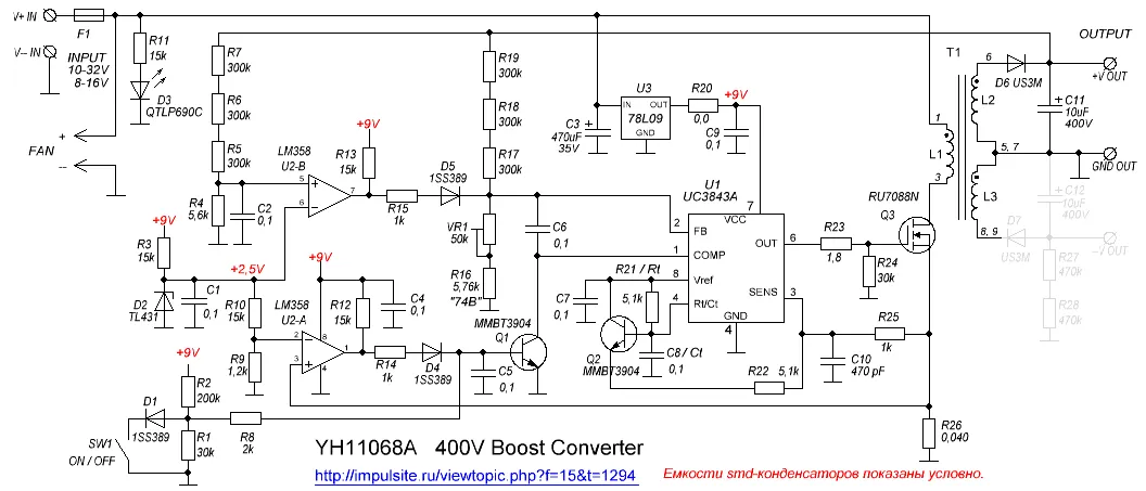
Looking at the components, we have:
-
78L09, a 9V regulator - power supply for the switching IC and other components
-
UCS3843B, switching supply control IC
-
LM393, op amp
-
A few diodes and a zener reference voltage.
On the output side, we’ve got two diodes.

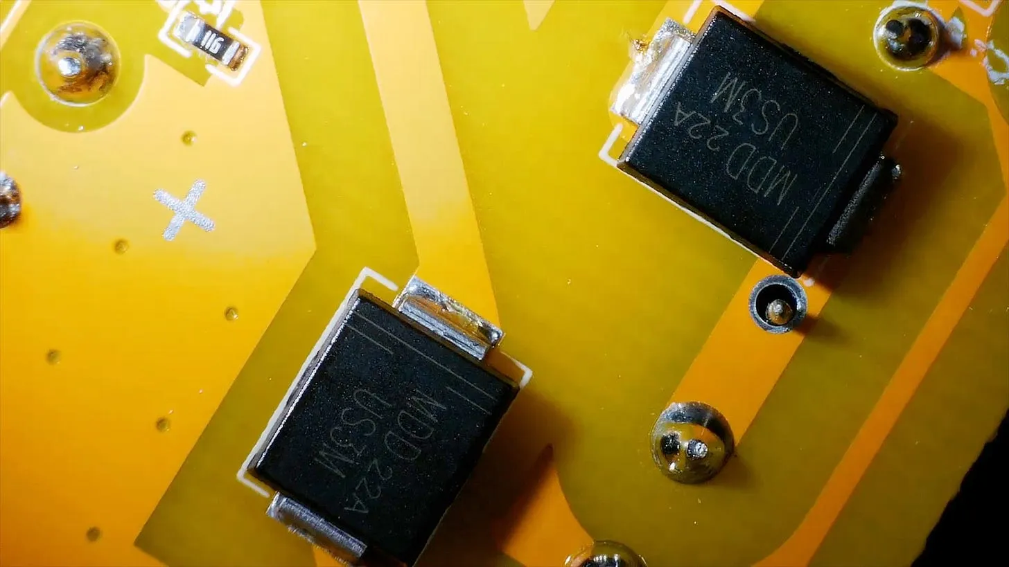
I tested both of these, the one for the positive rail seems to be fine. The one for the negative rail is pretty much a dead short.

On the input side, the MOSFET - is also dead. Drain and source are essentially shorted - looks very much like some of the MOSFETs I’ve killed myself…

I’ve ordered a couple of replacement boards. Hopefully they will arrive soon, and we can finally do the experiment we set out to do: lighting those LED filaments properly.
You can watch the video of me troubleshooting this board here:
And the previous video is here:
Related Posts
Whats wrong with my lightbulbs - In the saga of my beleaguered light bulbs, I've found myself knee-deep in electrical components and a fair bit of frustration. Of the four LED bulbs I invested in, only one survives unscathed, while another's flickering demise is imminent. My investigation revealed overheating bases, resilient capacitors, and an interesting LED filament setup. Ultimately, it seems one LED strip in the bulbs went open circuit, setting off a cascading failure. It's been a journey through minor electrical engineering heartbreak, with some messy disassembly and a sprinkle of high voltage excitement!
The PCBs are in production - what have I messed up? - After some stress and trepidation, I finally took the plunge and sent my PCB design off for manufacturing. My design centers around building a large seven-segment clock with LED filaments. Jumping hurdles such as voltages, pin usage, and limiting the load on my power supply, I've settled on the ESP32 as the system's heart and come up with a final circuit design. While doing this, I've quickly realized I could improve my layout and fixed a small mistake. Also, I've prepared for either types of LED filaments - the high-voltage ones or the larger, 3v ones. However, I did bungle up a couple of things on the enable line of the shift registers and board layout. But hey, this is a learning curve, right? Can't wait to get the boards and see what other exciting errors surface!
More fun and games with high voltage - Hey everyone! I know it's been a while since the last video, but things have been crazy busy with shipping off the ESP32 Rainbows. Lately, I've been diving into the world of high voltage again. My last endeavor with a high voltage board led to some gnarly waveforms and flickering LEDs, so I tested with beefy resistors but wasn't thrilled with the results. Fortunately, I've found some nixie tube driver boards that work wonders with LEDs, providing smooth output with little ripple. Still, playing with the old boards has its thrill—hello, 787 volts and some wild sparks! Stay tuned for more high voltage adventures!
Dave come see - it's beautiful man - Hey folks, I revisited my flame lamp project from 2020 and gave it a serious upgrade - we're talking a leap from 300 to a whopping 1024 LEDs thanks to these nifty flexible WS2812 panels. I've kitted it out with a versatile PCB from my Crystal Balls project, tackled power injection challenges and kept things cool with a current-limiting power supply. I had to wrestle with 3D printing and getting the panels to behave inside the lamp's tube, but the end result? A mesmerizing blaze of colors with gorgeous fire effect, all orchestrated by the WLED software. It's like my very own Phoenix rising from the 2020 ashes. Curious to see this electronic inferno come to life? Check out my videos for the full, fiery scoop!
Hue Light Hack - In a fun-filled deep dive into a Philip's Hue Color light bulb, I disassembled, analyzed, and ultimately restored it to working order. Over the course of the hack, I dismantled the bulb’s interior, from the aluminum PCB to the tiny ICs on the logic board, gave a detailed breakdown of their functions and even reverse engineered the signals controlling the colors. Most of the colors worked out pretty well, except for the dodgy yellow. Also, I tried running the hacked bulb setup with my old Moonlamp project. It was a great challenge and an exciting journey!
Related Videos
800 volt DC DC converter - In this video, I tinker with high-voltage circuits to light up LED filaments salvaged from broken light bulbs. Using a makeshift setup with a MOSFET, inductor, diode, and smoothing capacitor, I explore switching at high frequencies to achieve bright light. However, limitations with low-voltage capacitors led to some explosive results. I also experiment with a DC/DC converter to reach higher voltages, but it too failed, leading to a troubleshooting session under the microscope. Despite these setbacks, I'll keep tinkering and waiting for replacement parts to continue my experiment.
High voltage fun and games... or is it? - I've been diving into some exciting high voltage experiments with filaments scavenged from old Philips boards. After tinkering around with a YH11068A voltage generator, I'm now exploring a new version based on the MC34063 IC. Alongside, I've found a super handy voltage/current meter that's been a great help. If you enjoy my nerdy adventures and want to support my quest for more techy gadgets, check out my Patreon or pop by our new shop. Oh, and joining our Discord community or newsletter is a great way to stay in the loop!
Not what I was expecting! Why are all my lightbulbs failing? - So, we've been dealing with a little epidemic of light bulb failures in the house. I took apart a couple of dead bulbs to get to the bottom of what's going on. Turns out, one of the bulbs is kind of flickering and faintly working, while another bulb's base gets surprisingly warm. After some poking around, I found the PCB inside the bulb has a bridge rectifier and a LED driver IC, but all components test out fine! The investigation took a turn when I checked the LED filaments with a makeshift power supply, and surprise surprise, some filaments are completely dead. Still not sure what's causing these failures, but it was fun to tinker!
Boosting USB 5V to Light Up LED Filaments: Real-Life Testing & Circuit Simulation - Learn how to build a USB-powered LED filament circuit using an ESP32 microcontroller and DC boost converter. This project explores the use of a gate driver, inductor, diode, and capacitor to create a circuit that can power multiple LED filaments from a 5V USB supply.
1024 LEDs - WLED Flame Lamp - Today we're elbow-deep in LEDs for another exciting project — we're building a high-resolution flame lamp! Kick-starting the endeavour with a 1024-pixel LED matrix, we proceed to throw in the towel with a faulty old flame lamp boasting a mere 300 LEDs. Mislabelled PCBs and questionable diodes keep us on our toes, making this undertaking a little more Sparky than usual. With the help of competitive soldering skills, a beefy 5V power supply and a 3D printer, we channel our inner Edison to bring our LED matrix to light. After a pinch of struggle, our LED matrix rollercoasters into a tube shape, faintly resembling our coveted flame lamp. Tune in to bask in the warm (or cool) glow of our LED flame lamp.
HELP SUPPORT MY WORK: If you're feeling flush then please stop by Patreon Or you can make a one off donation via ko-fi