🌈 ESP32-S3 Rainbow: ZX Spectrum Emulator Board! Get it on Crowd Supply →
View All Posts
read
Want to keep up to date with the latest posts and videos? Subscribe to the newsletter
HELP SUPPORT MY WORK: If you're feeling flush then please stop by Patreon Or you can make a one off donation via ko-fi
#AI #DEVELOPMENT BOARD #ESP32-S3 #HARDWARE DESIGN #INNOVATION #KICAD #PCB #PCB DESIGN #TECHNOLOGY #VIBE CODING

After ā€œvibe codingā€ a software-based vibing button in my last video, I decided to take things one step further: vibe-coding the actual hardware. The challenge? Let AI design a working ESP32-S3 development board, from scratch.

Tools of the Trade

For this experiment, I used Atopile — a tool that lets you define a hardware project using code and turns it into a KiCad PCB. I also enlisted Claude, an AI coding assistant that seemed to outperform Cursor for this task.

The Prompt

The board needed the basics: an ESP32-S3 module, USB-C power and data lines, a 3.3V regulator, reset and boot buttons, status LEDs, a quick connector, and the usual passives. I specified LCSC part numbers and 0603 sizes for resistors and capacitors, with GPIO 19 and 20 handling the USB data lines for proper differential routing.

Here’s the exact prompt I used:

I want to make an ESP32-S3 dev board.

We will need:
- ESP32-S3 module
- USB-C connector with 5.1K resistor on the CC lines
- 3.3V voltage regulator
- A red LED showing 5V is connected
- A green LED showing 3V3 is available
- A blue LED connected to a GPIO pin
- A QWIIC connector for peripherals
- Reset button
- Boot button
- Any additional passive components needed for the above
- There should be an RC circuit for the enable pin on the ESP32-S3 module

The USB-C should provide 5V power and the data lines should be connected directly to the ESP32-S3 module. Don't forget, there are normally 2 pins for each data line. These should both be connected to the ESP32-S3 module.

GPIO19 and GPIO20 on the ESP32-S3 module are USB D- and D+ respectively. Make sure these nets are labeled correctly so that differential routing works.

Use LCSC part numbers for all components. You will need to search the web for these. Use 0603 for all resistors and capacitors.

Use the command to add the component to the project.

echo "0" | ato create part -s <LCSC-ID>

Add each component one at a time to the main.ato file.

Run the ato build command after every change you make to check your work.

ato build

Be very careful with the pin names/numbers in the components - check that you are using the correct ones. Do not modify the components.

The AI took the prompt and started generating components and wiring instructions. To stay true to the spirit of ā€œvibe coding,ā€ I didn’t look at the code — I just kept saying ā€œyesā€ and watched what happened.

The AI Journey (aka, Chaos Ensues)

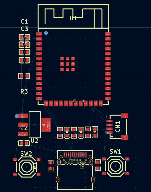
Initially, everything looked great. The build succeeded, all components were found and added. But when I opened KiCad… nothing was wired up.
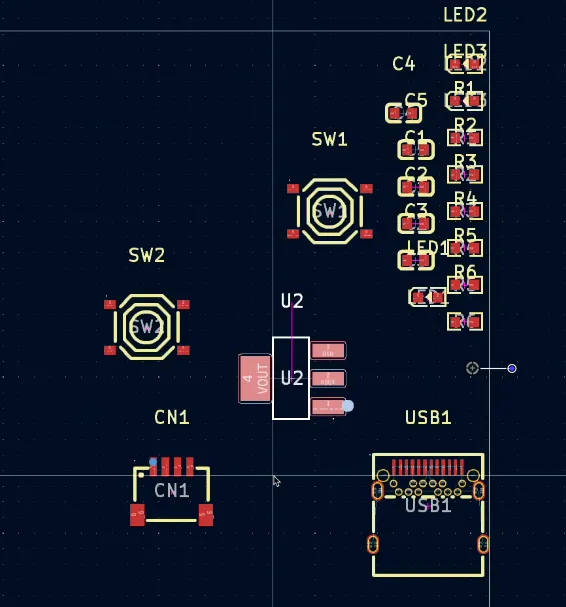
Where are the wires?

A quick nudge to Claude (ā€œyou forgot to connect anythingā€) got it back on track. After another build — success! Everything was wired.

R3 is missing it’s partner capacitor…

Well, mostly.

It forgot a capacitor in the RC circuit on the EN pin. Again, a quick note to the AI and it was fixed. I swapped in a more sensible 10K resistor (it had chosen 330Ī© for some reason), added some ground fills, and tidied up the layout.
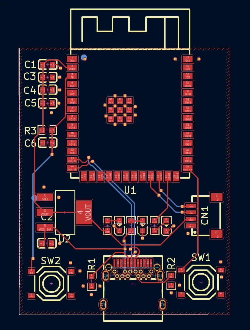
The Result

What we got was surprisingly functional:

  • AMS1117 regulator

  • Proper USB-C with CC resistors

  • Differential USB routing

  • Status LEDs

  • Decoupling caps galore

  • Reset and boot buttons

  • A functional RC circuit on EN

It’s not perfect (no schematic output yet unless you downgrade to KiCad 5), but as a first pass from an AI? Not bad at all.

Final Thoughts

Vibe-coding a PCB feels like the future. We’re close to being able to describe hardware in natural language and let the AI take care of the busywork. And while it’s not quite ready to replace a skilled engineer, it’s definitely ready to be your enthusiastic, if forgetful, assistant.

Next step? Should I send it off to PCBWay and see if it actually works?

Here’s the BOM for people interested in the components it picked:

Designator Footprint Quantity Value Manufacturer Part Number LCSC Part #
C1, C2, C3 C0603 3 Ā  Samsung Electro-Mechanics CL10A106MQ8NNNC C1691
C4, C5, C6 C0603 3 Ā  YAGEO CC0603KRX7R9BB104 C14663
CN1 CONN-SMD_4P-P1.00_SM04B-SRSS-TB-LF-SN 1 Ā  JST Sales America SM04B-SRSS-TB(LF)(SN) C160404
LED1 LED0603-RD 1 Ā  Hubei KENTO Elec Blue light 0603 C2288
LED2 LED0603-RD 1 Ā  Foshan NationStar Optoelectronics NCD0603C1 C84264
LED3 LED0603-RD 1 Ā  Hubei KENTO Elec KT-0603R C2286
R1, R2 R0603 2 Ā  UNI-ROYAL 0603WAF5101T5E C23186
R3 R0603 1 Ā  TyoHM RMC060310KFN C269701
R4, R5, R6 R0603 3 Ā  UNI-ROYAL 0603WAF3300T5E C23138
SW1, SW2 SW-SMD_4P-L5.1-W5.1-P3.70-LS6.5-TL_H1.5 2 Ā  XKB Connectivity TS-1187A-B-A-B C318884
U1 WIRELM-SMD_ESP32-S3-WROOM-1 1 Ā  Espressif Systems ESP32-S3-WROOM-1-N16R8 C2913202
U2 SOT-223-3_L6.5-W3.4-P2.30-LS7.0-BR 1 Ā  Advanced Monolithic Systems AMS1117-3.3 C6186
USB1 TYPE-C-SMD_TYPE-C-24P-QCHT 1 Ā  SHOU HAN TYPE-C 24P QCHT C456013
#AI #DEVELOPMENT BOARD #ESP32-S3 #HARDWARE DESIGN #INNOVATION #KICAD #PCB #PCB DESIGN #TECHNOLOGY #VIBE CODING

Related Posts

Minimalist Microcontroller: Building a Bare-Bones Dev Board - In a thrilling DIY endeavour, I attempted to build the most minimalist ESP32 dev board possible. Diving deep into the schematic of the ESP32 S3 WROOM module, I chopped out the non-essentials and whittled our needs down to bare bones. The experiment saw me juggling USB data lines and voltage regulators, waving goodbye to an array of capacitors and connectors and boldly embracing the simplicity of direct connections. Despite a few hitches, the miniature Frankenboard came alive, proving that sometimes less is more...at least in the world of microcontrollers.
Crowdfunding Success - Was it worth it? - I embarked on a thrilling adventure of turning a nifty idea into a tangible product — the ESP32 Rainbow, a Sinclair Spectrum-inspired gadget that merges retro vibes with modern tech. With the brains of an ESP32-S3, capacitive touch, a built-in display, and some snazzy UV silk screen printing, it's a little marvel that got crowdfunded successfully. But, oh boy, was the journey enlightening — from grappling with pricing conundrums and the bureaucracy of certifications to the harrowing odyssey of international shipping. While it didn't line my pockets with gold, seeing people enjoy something I created is worth all the sweat and jitters. Would I do it again? Well, maybe if lightning strikes twice with another great idea.
Easy esp32 s3 dev board - Quick recap: I’m putting together a super simple ESP32-S3 dev board—there’s a video walkthrough, the full KiCad project on GitHub, plus the schematic and a slick 3D render of the assembled board.
ESP32-S3 Dev Board Assembly - I finally assembled our ESP32-S3 dev boards—used a stencil for easy SMD work, fixed a few tiny USB solder bridges with flux, and even hand-built one for fun. The EPAD isn’t required (per the datasheet), power LEDs look good, and on macOS you can spot it under /dev before flashing. A quick boot-button dance and the blink sketch runs great—full build and walkthrough in the video.
ESP32-S3 USB UAC - I turned my new ESP32‑S3 board into a USB Audio device. After a ninja LED fix and confirming the IMU and charging, I streamed mic audio over Web Serial (with a slick AI-made ā€˜Audio Studio’) and then via USB UAC. The mic sounds great, but the speaker is crackly over UAC—even though I2S WAV playback is perfectly clean. ESP-IDF worked; Arduino didn’t. Bonus annoyance: macOS vs Windows is a toggle, not a combo. Still, this board passes QA.

Related Videos

Minimalist Microcontroller: Building a Bare-Bones Dev Board - Dive into the fascinating process of building a minimal ESP32-based dev board, beginning with the ESP32-S3 Wroom module, and eliminating unnecessary components. Through soldering, wire connecting, and voltage testing, we reach a product that's compact, efficient and fully functional.
We don't need a DAC - ESP32 PDM Audio - In this video, I've made some fascinating explorations with the ESP32 S3 chips and TinyS3 boards from Unexpected Maker. Intriguingly, even without a DAC converter, S3 chips can produce an audio waveform. I've played around with a basic RC filter to reconstruct the analogue audio signal from a PDM signal. The result was quite impressive for a board without a native DAC! I also discussed the possibility of creating a simple amplifier using just a MOSFET as a switch. Finally, I gave a peek into some of my new boards from PCBWay and looked at how Delta Sigma modulation can be played with to recover original data. It's all quite a fun foray into the world of circuitry and audio signals!
I Designed My Own ESP32-S3 Dev Board… and It Actually Worked! - I finally assembled my super simple ESP32‑S3 dev board—voltage regulator, reset button, three status LEDs (5V, 3.3V, and a GPIO blinker), and all pins broken out. I showed two build methods: stencil + hot-plate reflow (quick, with a few USB bridges to clean up) and full hand-solder under the microscope, complete with the rigorous ā€˜solid’ test. Soldered the ESP32‑S3 module (skipping the center thermal pad unless you need it), plugged in, got power LEDs, confirmed USB enumeration, flashed a blink sketch, and we’ve got a blinking LED. Next up: turning this basic dev board into something more professional for production.
ESP32-S3 - Which Pins Are Safe To Use? - In this video, I've decided to dive deep into the ESP32-S3, a module ruling my lab recently due to its plug-in-and-play functionality, and the flexibility offered by its GPIO matrix. However, working with it requires vigilance, especially with regard to the strapping pins and USB data pins, among others. Discovering such quirks, I've encountered unexpected values, short glitches and the occasional code crash. To help you avoid these bumps, I've documented everything I've learned on my GitHub repo, where I'm inviting you, my fellow makers and engineers, to contribute your valuable experiences and findings. After a minor hiccup with my ESP32-TV, expect an updated PCB design, courtesy of PCBWay. Explore the ESP32-S3 with me, and let's unravel its secrets together, one pull request at a time.
ESP32-S3 USB UAC Audio Device - does it work? - Time for an audio project: I took my PCBWay ESP32‑S3 board for a spin—fixed the common anode/cathode LED mix‑up, verified the IMU and battery charger, then tested an I2S PDM mic and tiny speaker with a Web Serial Audio Studio (scope, spectrogram, tuner). I also turned it into a USB UAC device in ESP‑IDF: the mic is clean, but speaker over UAC is crackly (Mac/Windows toggle oddity); direct I2S WAV playback is perfect, so the hardware passes QA.
HELP SUPPORT MY WORK: If you're feeling flush then please stop by Patreon Or you can make a one off donation via ko-fi
Want to keep up to date with the latest posts and videos? Subscribe to the newsletter
Blog Logo

Chris Greening


Published

> Image

atomic14

A collection of slightly mad projects, instructive/educational videos, and generally interesting stuff. Building projects around the Arduino and ESP32 platforms - we'll be exploring AI, Computer Vision, Audio, 3D Printing - it may get a bit eclectic...

View All Posts