In a previous project, I made an ESP32 pretend to be a USB webcam.
This time, I wanted to do it properly - turn it into a real USB webcam with a real camera.
I also wanted to push things a bit further - I’ve got an I2C thermal camera module - why not turn that into a USB camera?
The ESP32S3 has native USB support, which means it can present itself directly as a USB device - this opens up a whole world of possibilities.
For USB video, I’m using USB UVC (USB Video Class). I’m also sticking to MJPEG to make things simple.
The nice thing about MJPEG is that it’s not a video codec in the traditional sense — it’s just a stream of individual JPEG images, sent one after another over USB.
Simple case: a normal camera module
Many ESP32-compatible camera modules already output JPEG-compressed images.
That means the “encoder” part of the webcam is basically free:
Our code turns into this:
- Capture a JPEG frame from the camera
- Hand the JPEG bytes to the USB stack
- Repeat
You really can’t get much simpler than that.
You can use any S3 dev board - there are some nice ones that have built in cameras, but you could use a standard dev board and a camera module.
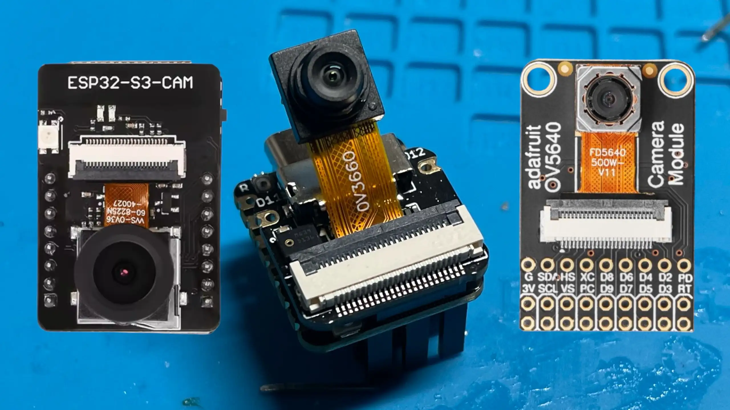
What you can’t use is the old ESP-CAM boards - firstly these don’t have USB and secondly the standard ESP32 doesn’t have native USB support.
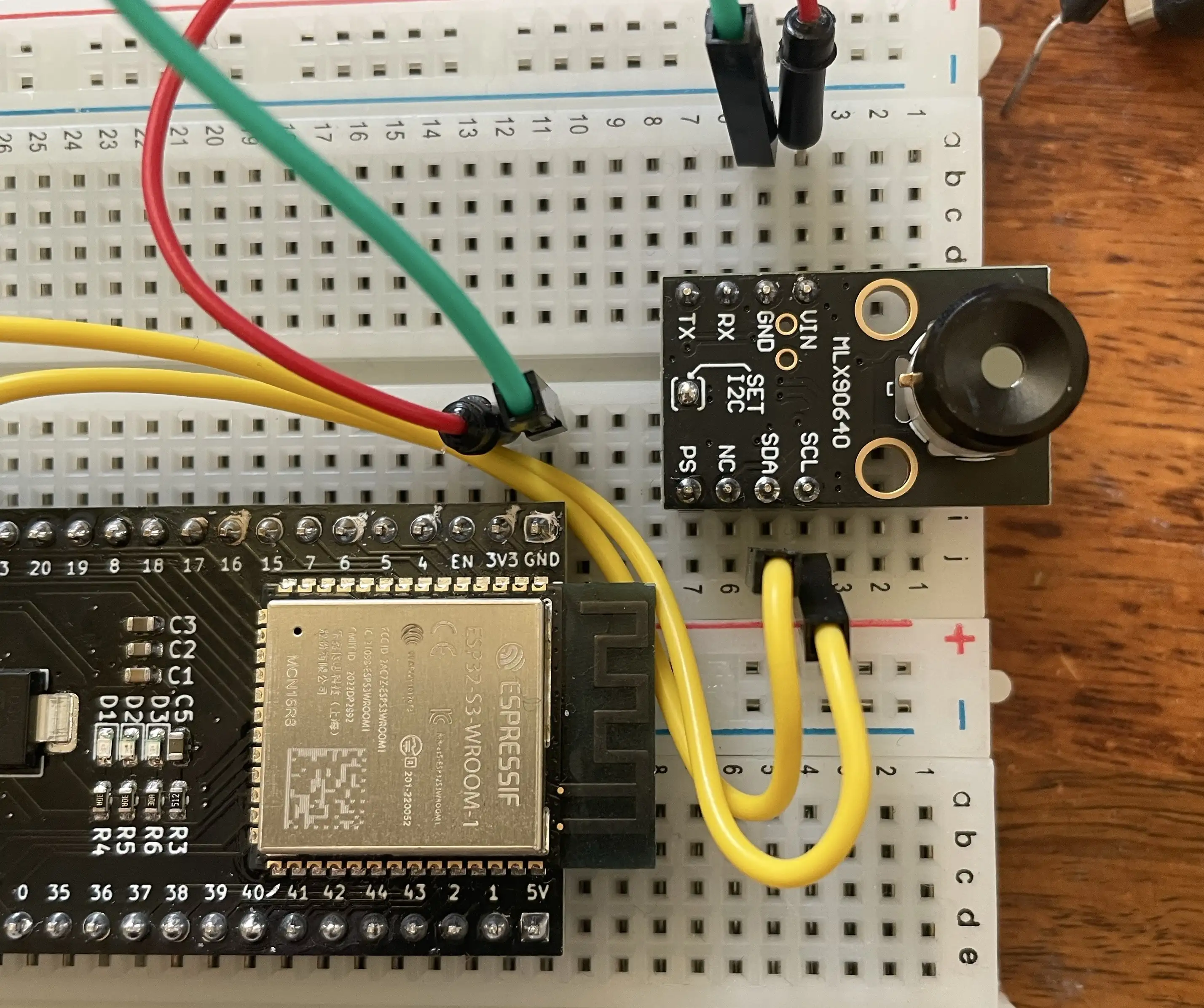
Moving to thermal: a 32×24 infrared camera
The thermal camera is where things get interesting.
I’m using an MLX90640. This module outputs a 32×24 pixel temperature image over I2C. That’s just 768 pixels total - really tiny and not very usable raw.
But it is enough data to work with.
Our new code flow is:
- Read the raw thermal image over I2C
- Convert temperatures to grayscale or false colour
- Scale the image up to 320×240
- JPEG encode it
- Stream it over USB using UVC
I2C debugging (and a reminder to myself)
Before any of it actually worked, I managed to lose a fair bit of time debugging what I thought was an I2C software problem.
- I scanned addresses.
- Checked pull-ups.
- Tried different voltages.
- Swapped code around.
Eventually, I looked at the board under a microscope abd found that it was just a dodgy solder joint on the on-board 3.3 V regulator.
You can see a detailed post on this here
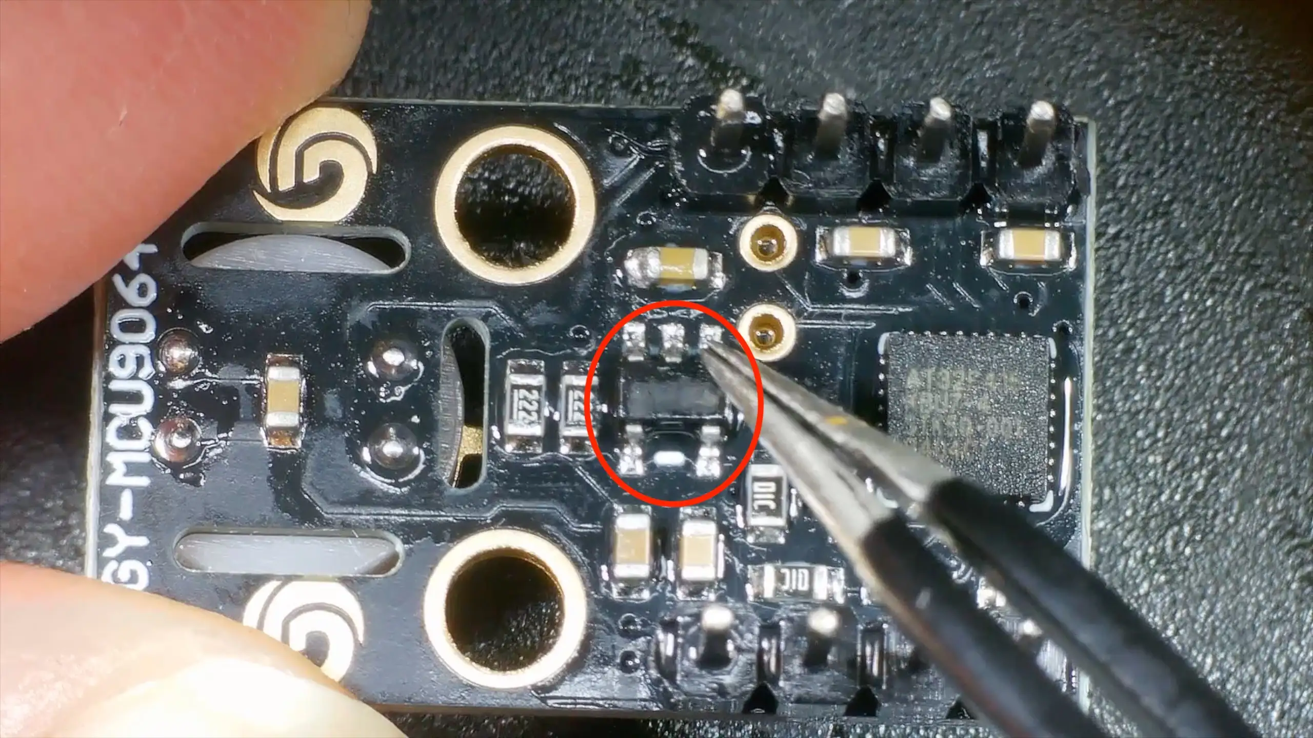
This particular thermal camera board includes:
- Built-in I2C pull-up resistors (2.2 kΩ to 3.3 V)
- An on-board 3.3 V regulator
In theory, that means the board expects to be powered from 5 V, feeding the regulator.
In practice, the regulator is a low-dropout device (around 120 mV dropout at 100 mA), so powering the board directly from 3.3 V worked just fine.
Importantly, because the pull-ups are tied to the 3.3 V rail, there are no weird voltage levels on the I2C bus even when powered this way - which does make me wonder how well it would work with a real 5v logic device.
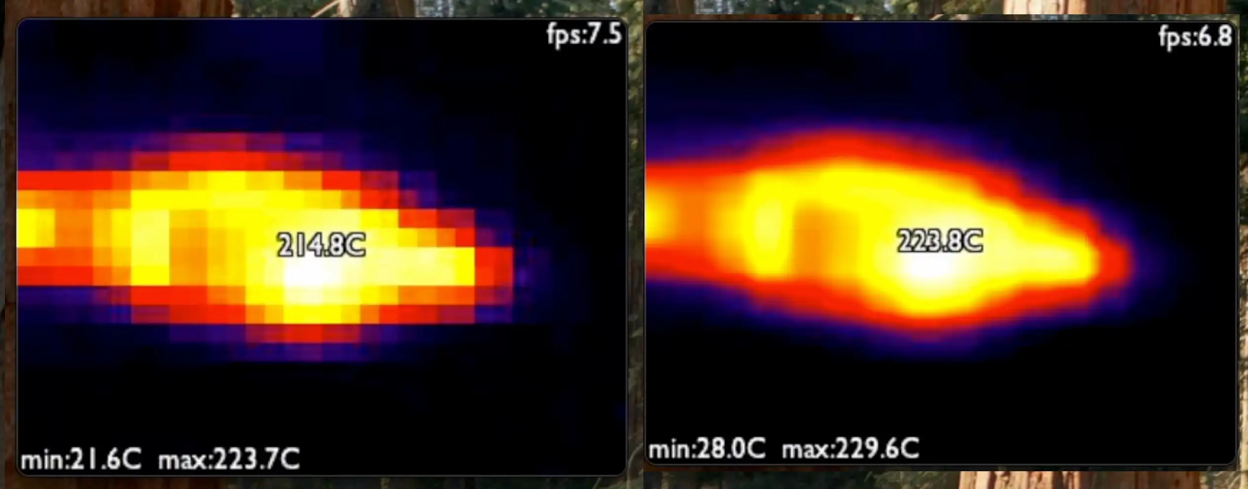
Making 32×24 pixels usable
Once the thermal data is coming in reliably, the next problem is obvious:
32×24 pixels is tiny.
The solution is to scale it up by a factor of 10× in each direction, producing a 320×240 image that fits nicely into a webcam frame.
I implemented two scaling options:
- Nearest neighbour: very fast, but can look a bit blocky
- Bilinear scaling: smoother, still fast enough on the ESP32-S3
Both give surprisingly good results, and once the image is scaled and colour-mapped, you’d never guess it started life at such a low resolution.
JPEG encoding and USB streaming
After scaling, the image is JPEG-encoded and sent over USB using the UVC stack.
From the host computer’s point of view, this is just a normal webcam:
- Works in standard camera apps
- No custom drivers
- No special software
Despite the low input resolution, the frame rate is perfectly usable, and the ESP32-S3 has more than enough performance to keep everything running smoothly.
You can see it all in actiion here - it’s pretty cool (or hot!).