🌈 ESP32-S3 Rainbow: ZX Spectrum Emulator Board! Get it on Crowd Supply →
View All Posts
read
Want to keep up to date with the latest posts and videos? Subscribe to the newsletter
HELP SUPPORT MY WORK: If you're feeling flush then please stop by Patreon Or you can make a one off donation via ko-fi
#ARDUINO #C++ #DISPLAY #EMBEDDED #ESP32 #ESP32-C3 #GRAPHICS #I2C #MICROCONTROLLERS #OLED #SSD1306 #U8G2

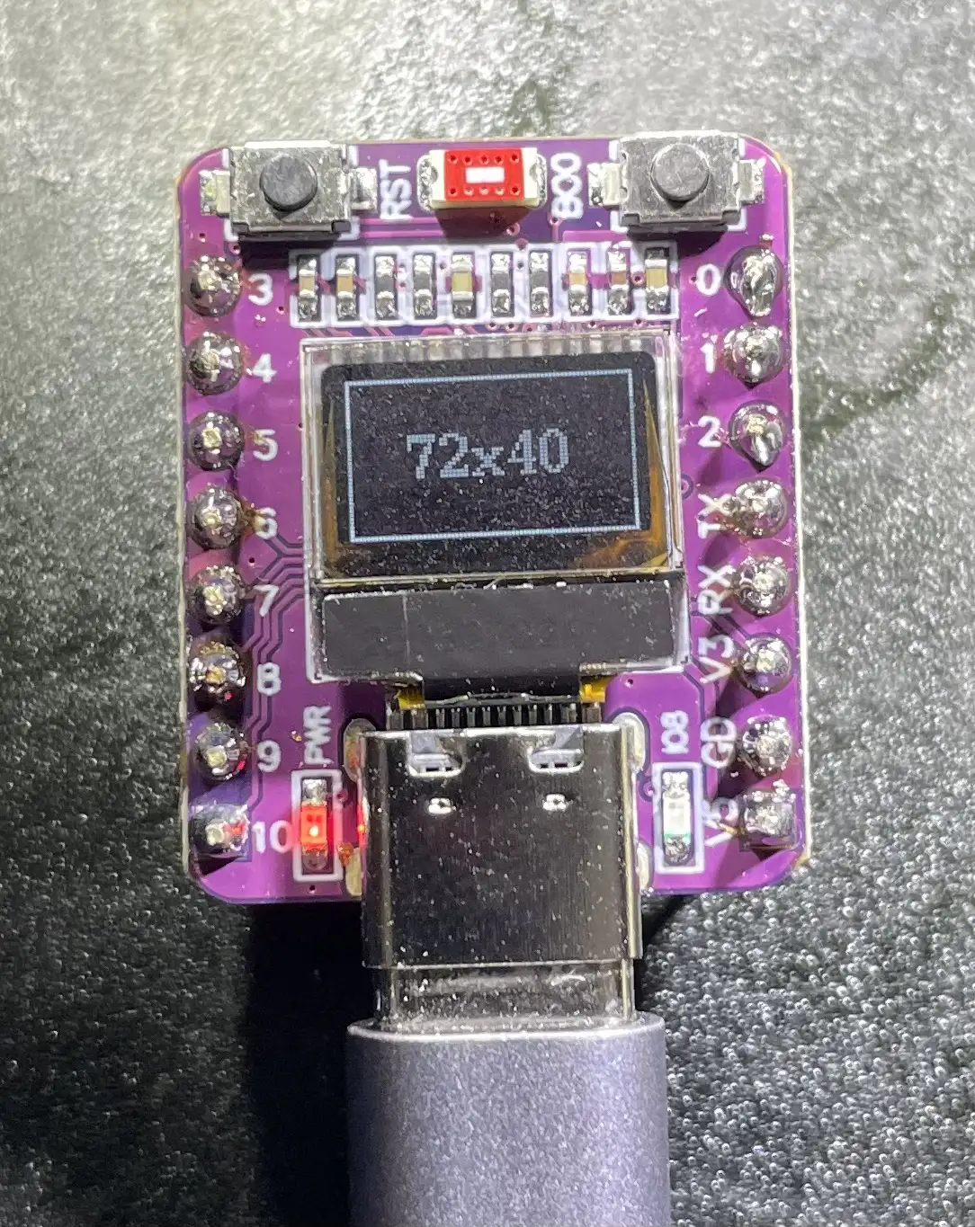
I’ve ended up with a bunch of these nice little ESP32-C3 modules.

I’m a bit late to the party with them, so other people have done a lot of heavy lifting working out how to drive the display. I followed this blog.

The only thing I didn’t quite like was the slight bodge in his drawing code where he used the U8G2_SSD1306_128X64_NONAME_F_HW_I2C class and then offset his code to work for 70x40 size display.

There’s a quick fix to not having an appropriate constructor with the right size - digging into the U8g code the parts are all there for us to declare our own and get a slightly neater bit of code.

Display Working

#include <U8g2lib.h>
#include <Wire.h>

class U8G2_SSD1306_72X40_NONAME_F_HW_I2C : public U8G2 {
  public: U8G2_SSD1306_72X40_NONAME_F_HW_I2C(const u8g2_cb_t *rotation, uint8_t reset = U8X8_PIN_NONE, uint8_t clock = U8X8_PIN_NONE, uint8_t data = U8X8_PIN_NONE) : U8G2() {
    u8g2_Setup_ssd1306_i2c_72x40_er_f(&u8g2, rotation, u8x8_byte_arduino_hw_i2c, u8x8_gpio_and_delay_arduino);
    u8x8_SetPin_HW_I2C(getU8x8(), reset, clock, data);
  }
};

U8G2_SSD1306_72X40_NONAME_F_HW_I2C u8g2(U8G2_R0, U8X8_PIN_NONE, 6, 5);

int width = 72;
int height = 40;

void setup(void)
{
     delay(1000);
     u8g2.begin();
     u8g2.setContrast(255); // set contrast to maximum 
     u8g2.setBusClock(400000); //400kHz I2C 
     u8g2.setFont(u8g2_font_ncenB10_tr);
}

void loop(void)
{
    u8g2.clearBuffer(); // clear the internal memory
    u8g2.drawFrame(0, 0, width, height); //draw a frame around the border
    u8g2.setCursor(15, 25);
    u8g2.printf("%dx%d", width, height);
    u8g2.sendBuffer(); // transfer internal memory to the display
}
#ARDUINO #C++ #DISPLAY #EMBEDDED #ESP32 #ESP32-C3 #GRAPHICS #I2C #MICROCONTROLLERS #OLED #SSD1306 #U8G2

Related Posts

ESP32-S3 Dev Board Assembly - I finally assembled our ESP32-S3 dev boards—used a stencil for easy SMD work, fixed a few tiny USB solder bridges with flux, and even hand-built one for fun. The EPAD isn’t required (per the datasheet), power LEDs look good, and on macOS you can spot it under /dev before flashing. A quick boot-button dance and the blink sketch runs great—full build and walkthrough in the video.
ESP32-S3 Hardware SPI on the Adafruit ST7789 - I've had some commenters point out the issue with the slow display updates in my recent Arduino Nano ESP32 video. It turns out, the software SPI of the Adafruit_ST7789 library was the culprit. Lo and behold, the solution is simple - using the hardware SPI constructor of the library. Apparently, this isn't well documented, so I wrote some code to serve as reference for myself and others who might run into the same snags. Trust me, the difference in speed is absolutely bonkers. Check out the video to see the magic in action.
1 touch pin 8 touch pads - To make my ESP32 ZX Spectrum touch keyboard work even better, I needed to ensure every key was independent. The ESP32-S3 only has 14 touch pins, so I’ve been using a matrix approach. While this works well, it struggles with key combinations, critical for the ZX Spectrum. I explored touch detection and experimented with analog multiplexer ICs (4051 series) to expand the touch pins. Initial tests were promising. After prototyping with breadboard-friendly versions and ordering parts, the new keyboard was not only functional but exceeded my expectations. Scanning the keyboard now takes around 20ms, and the solution is ready for production. This was the last big challenge, and I’m thrilled with the results!
Easy esp32 s3 dev board - Quick recap: I’m putting together a super simple ESP32-S3 dev board—there’s a video walkthrough, the full KiCad project on GitHub, plus the schematic and a slick 3D render of the assembled board.
Minimalist Microcontroller: Building a Bare-Bones Dev Board - In a thrilling DIY endeavour, I attempted to build the most minimalist ESP32 dev board possible. Diving deep into the schematic of the ESP32 S3 WROOM module, I chopped out the non-essentials and whittled our needs down to bare bones. The experiment saw me juggling USB data lines and voltage regulators, waving goodbye to an array of capacitors and connectors and boldly embracing the simplicity of direct connections. Despite a few hitches, the miniature Frankenboard came alive, proving that sometimes less is more...at least in the world of microcontrollers.

Related Videos

I Built My Own ESP32-S3 Board… And It Actually Works! - I finally assembled my super simple ESP32‑S3 dev board—voltage regulator, reset button, three status LEDs (5V, 3.3V, and a GPIO blinker), and all pins broken out. I showed two build methods: stencil + hot-plate reflow (quick, with a few USB bridges to clean up) and full hand-solder under the microscope, complete with the rigorous ‘solid’ test. Soldered the ESP32‑S3 module (skipping the center thermal pad unless you need it), plugged in, got power LEDs, confirmed USB enumeration, flashed a blink sketch, and we’ve got a blinking LED. Next up: turning this basic dev board into something more professional for production.
ESP32 Audio Monitor using TFT_eSPI (TTGO) - Unable to generate a summary because no transcript was provided. Share the transcript or a brief outline of the video and I’ll craft a concise, author-voiced summary.
My ESP32S3 Thinks It's a WebCam! - I turned a vanilla ESP32-S3 dev board into a USB UVC webcam that doesn’t use a camera at all—first streaming a static test card, then an animated GIF, and finally a real-time Pong game. The ESP32 pre-decodes GIF frames to RGB, JPEG-encodes them, and streams MJPEG, and for the live game it renders to a framebuffer, JPEG-encodes in ~23 ms, and just about hits 30 fps. There’s room to optimize (dual-core draw/encode), and this approach is great for dashboards, sensor visualizations, or testing video pipelines. Shout out to PCBWay for the boards—they turned out great.
Drones and Lasers? - It’s been a while since we’ve done an unbagging, and I’ve clearly been on an AliExpress bender. Big thanks to PCBWay for fueling the chaos. Today’s haul: a pair of tiny ESP32‑C3 OLED modules (no idea why I ordered two, but here we are), a finger pulse/SpO2 sensor, a USB‑C PD trigger with DIP switches that happily serves up 5/9/12/15/20V (1+3 gives 20V—very handy), an INMP441‑compatible MS8625 mic, a surprisingly nice transparent clock with temp/humidity, a couple of rechargeable nightlights that only charge on dumb USB because there are no CC resistors, a laser and matching detector (pew pew!), and, bizarrely, a “smart” insulated tea mug that lights up and says 20°. Lots of little projects to spin out from this lot.
I Spent Hours Debugging My Software… - Quick bench update: I tried to get a 32×24 pixel IR module talking over I2C and it just would not play ball—pull-ups, library swaps, address scans, nothing. First silly mistake was not bridging the I2C jumper. Even after fixing that, still dead. Under the microscope I spotted the real issue: poorly soldered pins on the IC. A quick reflow and some IPA cleanup later, it sprang to life. Moral of the story: if yours won’t talk, check the underside soldering. Project video coming soon.
HELP SUPPORT MY WORK: If you're feeling flush then please stop by Patreon Or you can make a one off donation via ko-fi
Want to keep up to date with the latest posts and videos? Subscribe to the newsletter
Blog Logo

Chris Greening


Published

> Image

atomic14

A collection of slightly mad projects, instructive/educational videos, and generally interesting stuff. Building projects around the Arduino and ESP32 platforms - we'll be exploring AI, Computer Vision, Audio, 3D Printing - it may get a bit eclectic...

View All Posts