🌈 ESP32-S3 Rainbow: ZX Spectrum Emulator Board! Get it on Crowd Supply →
View All Posts
read
Want to keep up to date with the latest posts and videos? Subscribe to the newsletter
HELP SUPPORT MY WORK: If you're feeling flush then please stop by Patreon Or you can make a one off donation via ko-fi
#ALIEXPRESS FIND #BISTABLE CHOLESTERIC DISPLAY #DIY #ELECTRONICS #TEARDOWN

You can watch a full video version with more details here.

I’ve had one of these little gadgets sitting in my AliExpress box of bits for quite a while. The other day I saw Big Clive do a teardown on one, so I thought it was time to dig mine out and see what makes it tick.

The device is a bistable cholesteric display—a type of screen that lets you draw or write on it and then clear everything with the press of a button. Simple, cheap, and surprisingly fun.

What Is a Bistable Cholesteric Display?

Inside the display are two transparent layers sandwiching a special liquid crystal material. These cholesteric crystals have two stable states:

  • Transparent in one state.
  • Scattered/opaque when a high voltage is applied, causing the crystals to align.

Because the crystals are bistable, they don’t need constant refreshing like an LCD or OLED—once the image is written, it stays there until you clear it. That’s why the device can run for ages on a coin-cell battery.

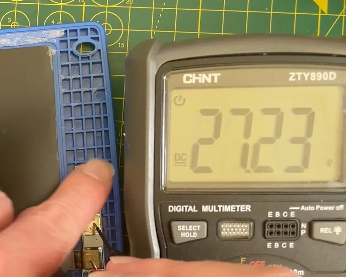
Measuring the Clear Voltage

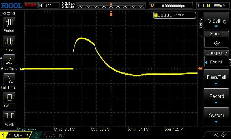
Of course, I had to see what was actually happening electrically. Hooking the display up to a multimeter showed it jumping up to around 30 volts when the clear button was pressed.

Multimeter Reading

On the oscilloscope, I captured a nice trace with a peak at 26.8 volts—so roughly 30V is what’s being dumped into the crystals to reset the display.

Oscilloscope Reading

Forcing It With a Power Supply

Curiosity got the better of me, so I decided to try it with a power supply set to 30V. After scribbling some random squiggles on the screen, I touched the supply across the contacts… and it worked! The screen cleared instantly.

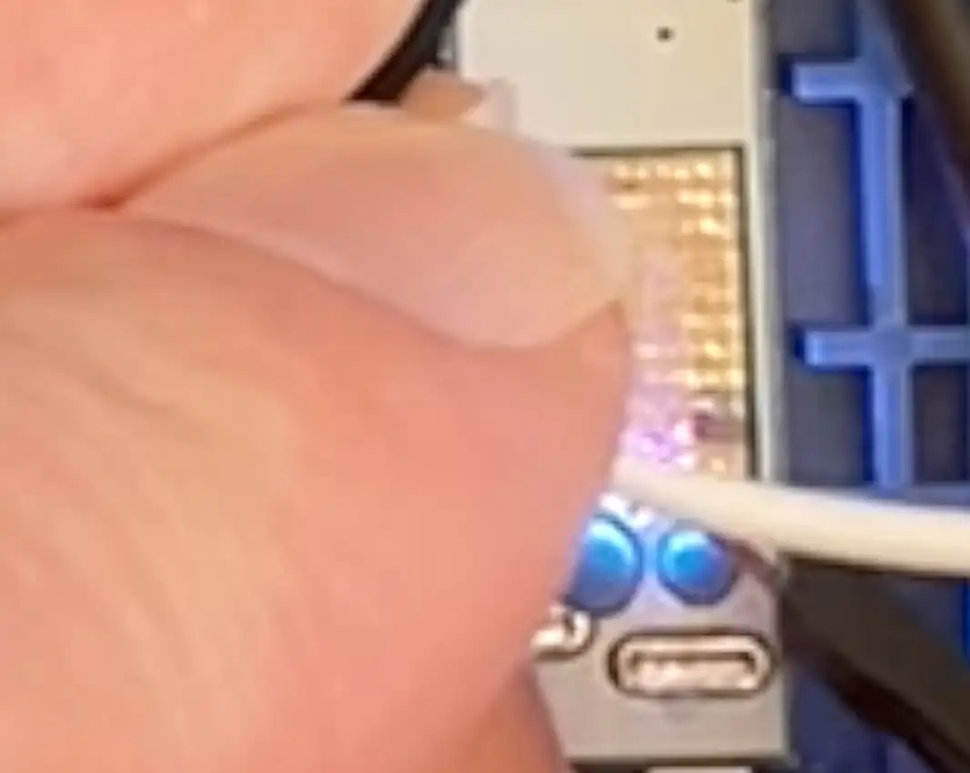
Polarity seems to matter, though. Connected one way, everything cleared nicely. Reversing the leads caused a spark—oops. I can still clear the display using my power supply, but the PCB is now toast.

Annoyingly, my finger got in the way, so we can only see the flash of the spark.

Spark

Lesson learned: don’t reverse the voltage.
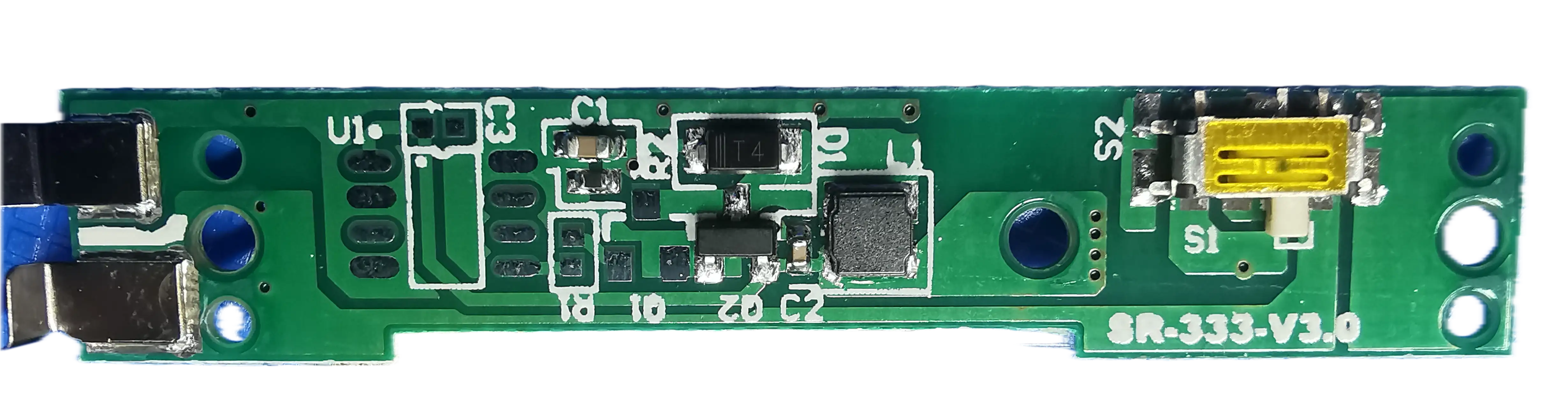
Simple Construction

The build is about as simple as you’d expect. Two sheets, some liquid crystal sandwiched in between, and a tiny PCB with the button and battery connection. That’s it.

PCB Closeup

And here’s my attempt at a schematic.

Schematic

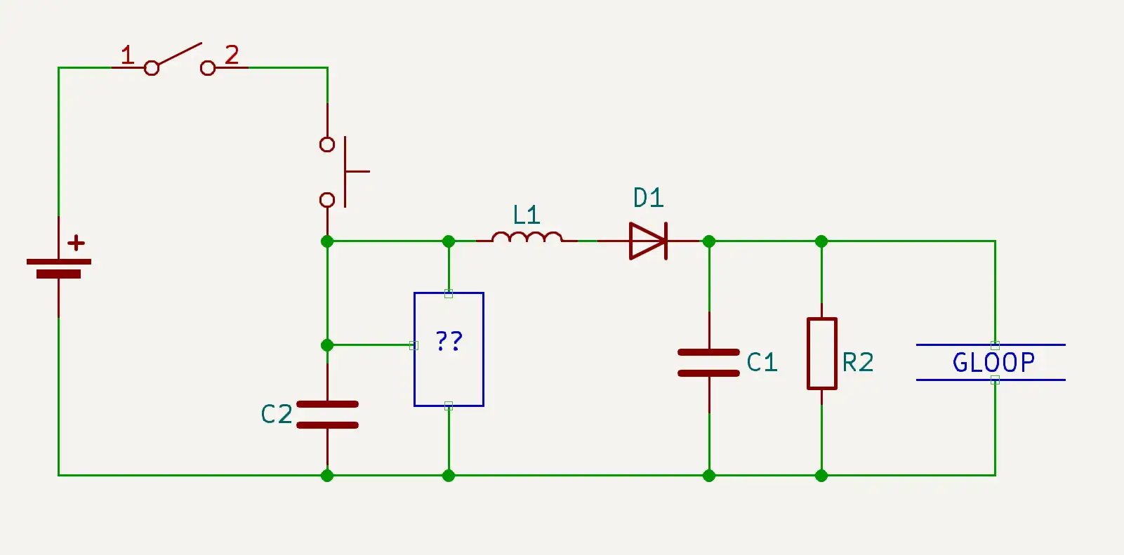
I’m not sure if it’s correct, but it’s a good starting point.

Final Thoughts

These bistable cholesteric displays are fun little bits of kit. They’re simple, low-power, and seem to work well enough.

If you’d like to buy one, you can find them on AliExpress.

#ALIEXPRESS FIND #BISTABLE CHOLESTERIC DISPLAY #DIY #ELECTRONICS #TEARDOWN

Related Posts

High voltage coin cell - I blew up the original PCB on a bistable cholesteric display, so I built a coin-cell Joule thief to crank out 27V and bring it back to life. A simple two-inductor setup with a 27V Zener does the trick—about 10 mA while the button’s held. Then I got fancy with a regulated version (just one extra transistor) that tops the cap to 27V and basically idles—average draw lands around 1.53 mA. It’s neat, tiny, and perfect for this low-current reset job. Full build and measurements are in the video.
I Built a 27V Circuit to Fix This $3 Gadget - I revived a cheap scribble pad by swapping its fried board for a tiny PCB that boosts a coin cell to 27 V—enough to cleanly reset the bistable LCD. It’s a Joule Thief with Zener regulation and twin 220 µH inductors (mounted in opposite orientations), pulling ~17 mA during charge and ~7 mA while regulating. It’s coin-cell friendly, works great, and just needs a bit of case surgery for a perfect fit.
Brain Surgery - I cracked open a cheap Halloween toy, found the super-simple LED + LR41 setup with the arm-as-switch trick, and swapped the ‘empty head’ for my own CH32V003 + buzzer PCB. Now it screams as well as shines—powered by a small lithium cell for extra volume because if you’re going to be annoying, do it properly. New schematic, new brains, same spooky vibes.
10 Cent Music Machine - I built a tiny coin‑cell music board around the $0.10 WCH CH32V003J4M6 (8‑pin, 48MHz RISC‑V, 16K flash/2K RAM). The PCB is just 16.3×11.7mm with a piezo buzzer and transistor, and in standby it sips 7–8µA. I did hit a snag: playback caused 130mA peaks that browned out a CR2032. A LiPo fixed it, but I really wanted coin‑cell, so I upped the buzzer’s base resistor to 10k, dropping peaks to 56mA and average to ~7mA—now it runs happily (and loudly) from a coin cell. Pro tip: if standby bricks programming, wlink can erase via power-off mode. I’m bit‑banging audio, published a simple MIDI→buzzer tool with a 1‑bit SFX generator, and all the code’s on GitHub.
Red Arcade Thing Repair - I resurrected a dead AliExpress arcade handheld by swapping the blown 3.3V regulator (I now own 99 spares), adding a TP4056 charger with Schottky diode isolation, and nursing a 0V LiPo back to life. A bit of hot-plate rework, tidier wiring, and—flip the switch—boom: it boots! It’s not pretty, but it’s alive again.

Related Videos

I Built a 27V PCB to Fix This $3 Display... - I resurrected the LCD writing tablet I blew up last time by designing a drop‑in PCB that generates a 27 V pulse to clear the screen. It’s a regulated dual‑joule‑thief variant with two magnetically coupled 20 µH inductors (soldered opposite ways), a 27 V zener for regulation, inrush limiting, and a few caps and a bleed resistor. I assembled it with PCBWay boards, tried both Voltera‑printed paste and manual SMD under the microscope, salvaged the blister button, and profiled it on the Nordic PPK—peaks ~18–19 mA, ~7 mA while regulating—totally coin‑cell friendly. It fits with a bit of mechanical fiddling, and now it scribbles and clears like new—almost a seamless repair… you’d never know I was here.
High Voltage Coin Cell - 27V Joule Thief - How much voltage can we squeeze out of a CR2025? Turns out… plenty! I built a little Joule-thief-style boost circuit with two 1 mH inductors, an NPN, a Schottky, a 27 V zener clamp, and a storage cap to zap my LCD pad clean at around 27 V. I profiled it with a Nordic power monitor: about 11 mA during the boost and ~9.28 mC per click—so tens of thousands of presses from one coin cell. Then I added a second transistor tied to the zener to auto-limit the drive, dropping hold current to about 1.5 mA—huge win. Scoped it (~38.7 kHz, base swinging to nearly -6 V), laid out a PCB, 1:1 print check for fit, and sent the gerbers off to PCBWay.
Look at My Shiny Crystal Balls - Custom ESP32 PCB With WLED. - Step right up, folks, for the grand unveiling of my shiny new crystal balls – yes, crystal balls. I've transformed ordinary AliExpress pieces into juggernauts of light and color, all powered by the splendid WLED software. Dive deep with me into the nitty-gritty of the underlying electronics and come face-to-face with the true beauty of voltage measurements (I promise, it's more riveting than it sounds). While the original circuit boards from AliExpress might not thrill, my beefed-up version invites gasps of wonder, with microphone-controlled LEDs throwing light in a million dazzling ways. Join me as I chronicle my journey through schematic revisions, components selection, and technological trickery – in short, the wild ride that has led to this epic macOS light show.
Dodgy circuit could have caused a fire! - So, I got this red mini handheld game thing from AliExpress and it died pretty quickly. After a bit of tinkering, I found that it still draws current but isn't turning on because of a dead battery and a burnt voltage regulator. I removed the faulty components and injected 3.3 volts directly into the system, and guess what? The screen lights up and it works, but there's no sound. Despite the hiccup with my microscope, which stopped recording some interesting bits, you get the picture. It's partly revived but not quite there yet. Big shout out to PCB way who help us out with PCBs!
787 Volts From a $2 Board! - Let's have some fun with high voltage experiments and LED filaments! I've been dabbling with 300-400 volts, testing out capacitor charging, and saving some flickery Philips bulbs. With a new ESP32 Rainbow project in the works and a nifty minimalist ESP32 S3 board arriving soon, there's lots going on. Despite some high ripple issues and quirky sounds from the modules, swapping to an old-school surface mount board provides smooth performance with almost no ripple. Join me as I explore the limits and potential projects with these LEDs. And for a shocking tidbit at the end, explore some high voltage calculations—it's electrifying!
HELP SUPPORT MY WORK: If you're feeling flush then please stop by Patreon Or you can make a one off donation via ko-fi
Want to keep up to date with the latest posts and videos? Subscribe to the newsletter
Blog Logo

Chris Greening


Published

> Image

atomic14

A collection of slightly mad projects, instructive/educational videos, and generally interesting stuff. Building projects around the Arduino and ESP32 platforms - we'll be exploring AI, Computer Vision, Audio, 3D Printing - it may get a bit eclectic...

View All Posts