🌈 ESP32-S3 Rainbow: ZX Spectrum Emulator Board! Get it on Crowd Supply →
View All Posts
read
Want to keep up to date with the latest posts and videos? Subscribe to the newsletter
HELP SUPPORT MY WORK: If you're feeling flush then please stop by Patreon Or you can make a one off donation via ko-fi
#ANALOG CIRCUITS #BISTABLE DISPLAY #BOOST CONVERTER #CHOLESTERIC LCD #COIN CELL #DIY #ELECTRONICS #HIGH VOLTAGE #JOULE THIEF #POWER PROFILING #TEARDOWN #ZENER DIODE

A while back, we tore down one of those fun bistable LCD displays—it was pretty interesting, but unfortunately, while experimenting, I blew up the PCB.

This PCB is dead

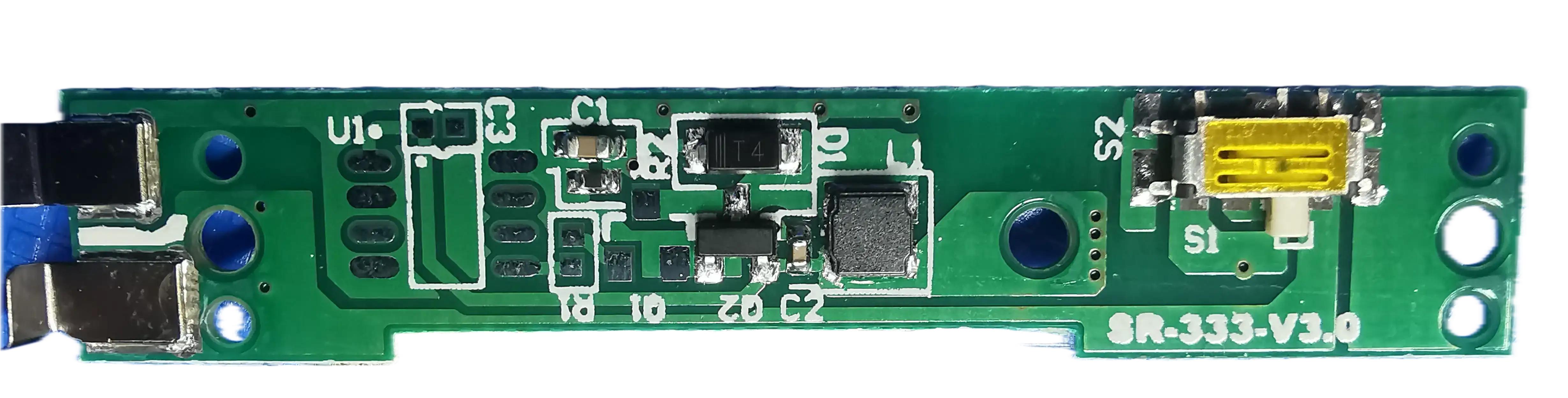
The PCB generates around 27 volts from the coin cell. There’s a mystery IC used to achieve this.

What’s the mystery IC?

You can read all about it in this post.

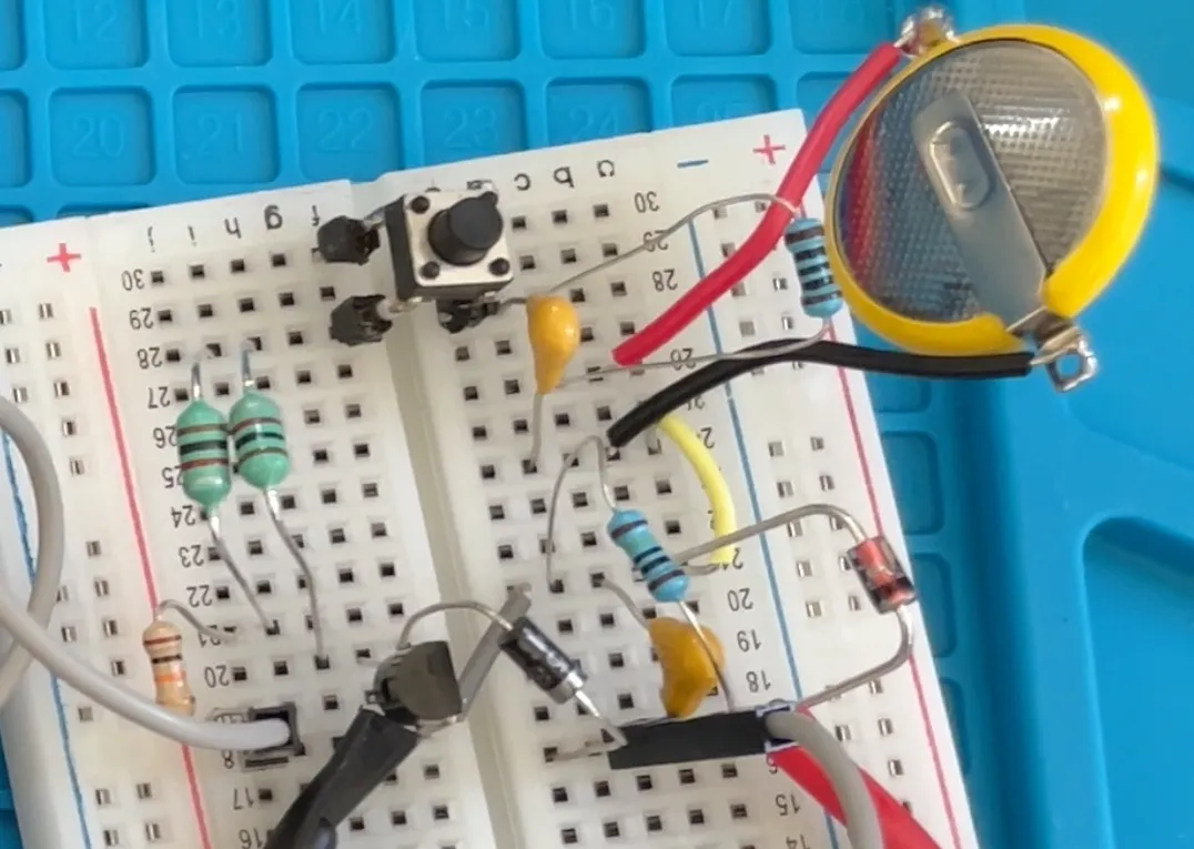
Since I broke it, I decided that I should try to fix it. I missed out on all the Joule thief excitement that seemed to be around on YouTube about 8 years ago, but I thought, why not give one a go - you can get quite high voltages out of them, and we don’t need much current to reset the display.

The actual Joule thief circuit is surprisingly simple—and there’s a great Wikipedia page that gives you a lot of details on how it works.

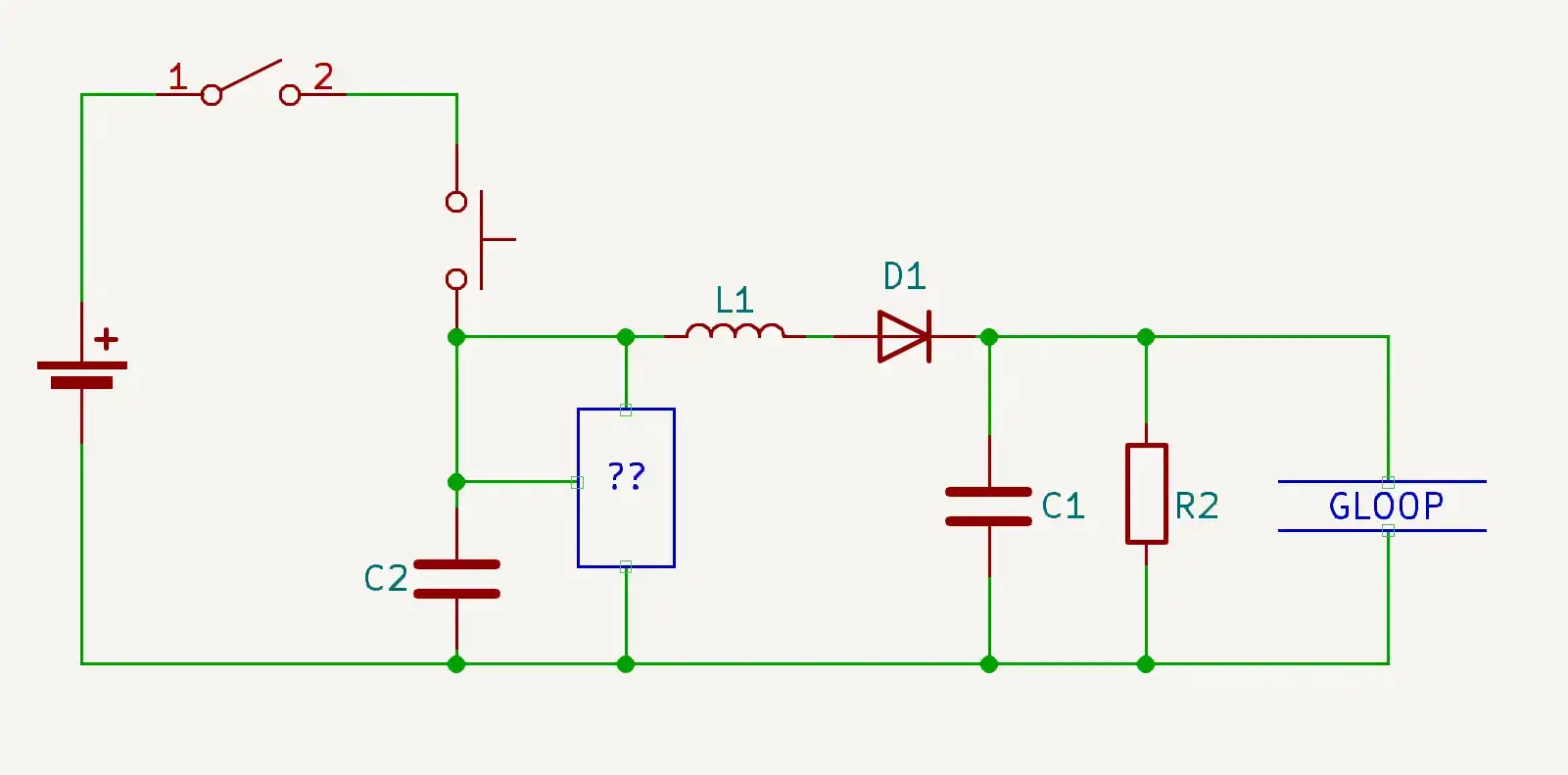
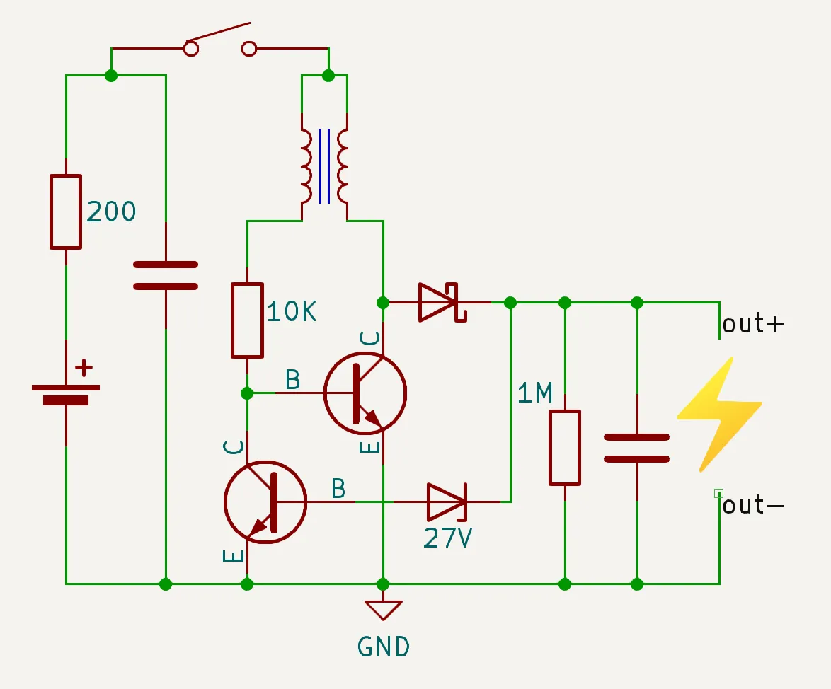
Here’s my initial circuit:

Simple Joule thief

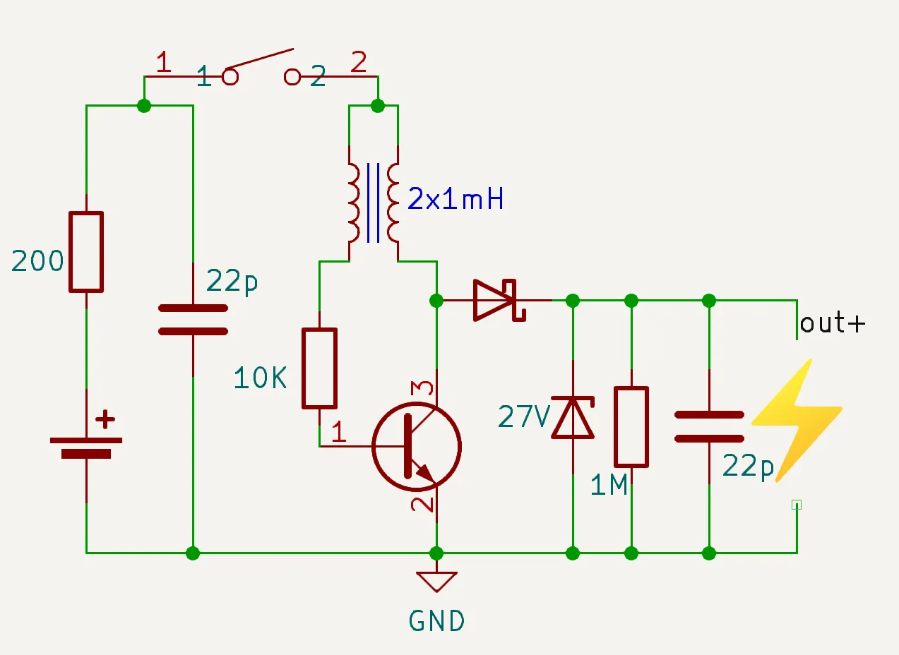
I’m using quite a large base resistor of 10K - normally you’d use around 1K. I’ve also got a series resistor in line with the battery to limit how much current we draw.

Apart from that, it’s a pretty standard Joule thief circuit.

On the output side, we have a 27V Zener diode to cap the voltage, a small capacitor that gets charged up, and a 1M bleed resistor so the voltage goes down after power is removed.

For the coils, I used two 1mH inductors. I could have taken a choke and wound some wire around it, but I got good results just from using two inductors.

Breadboard Joule thief

The circuit works nicely—we get 27V out of it without any problems!

27 volts!

This is more than enough to clear the bistable display.

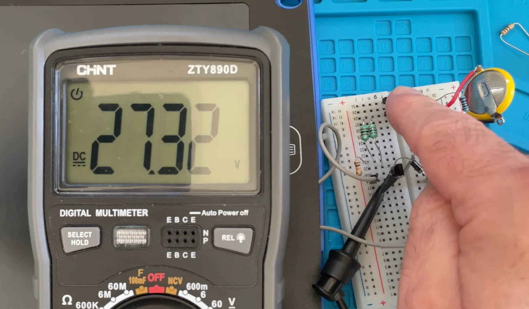
One thing I was interested in is how much current we are drawing from the coin cell, so I hooked up my Nordic power monitor and gave it a test.

Joule thief current draw

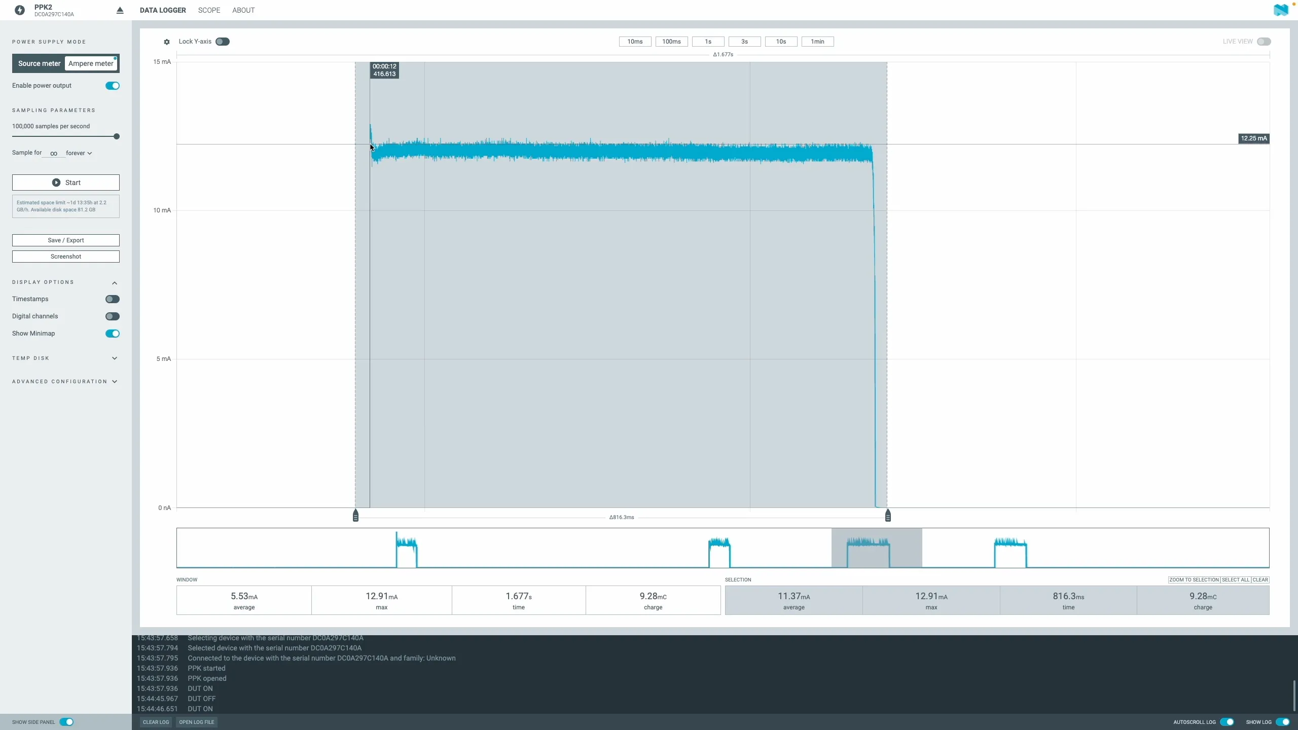
When we hold the button down, we draw around 10mA—which is not too bad for a coin cell - provided you don’t draw that much current for too long.

In theory (according to ChatGPT) we should be able to get 40-50,000 button presses out of one coin cell…

You can go a bit further with the Joule thief and create a regulated version — you just need another transistor.

Regulated Joule thief

This is a really efficient circuit—as soon as we hit 27V, we don’t need to provide power. This is perfect for our use case, where the output doesn’t really draw any current.

The power profile for this new circuit is really nice.

Regulated Power Profile

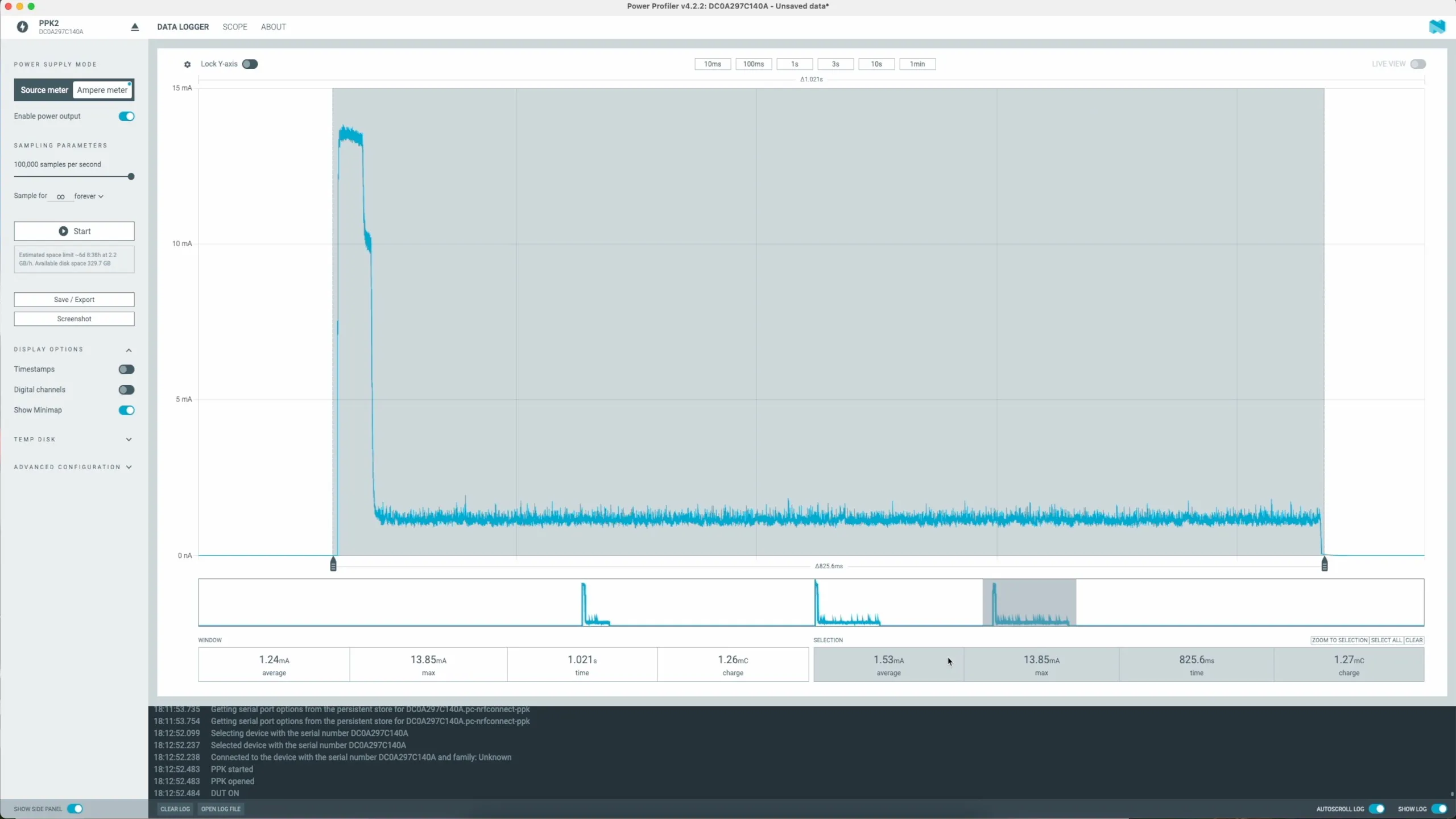
We have the initial spike up to 10mA and then almost immediately drop down. The average current for this version is 1.53mA—that’s pretty impressive!

You can watch the full exploration in this video here:

#ANALOG CIRCUITS #BISTABLE DISPLAY #BOOST CONVERTER #CHOLESTERIC LCD #COIN CELL #DIY #ELECTRONICS #HIGH VOLTAGE #JOULE THIEF #POWER PROFILING #TEARDOWN #ZENER DIODE

Related Posts

Tearing Down a Bistable Cholesteric Display - I recently dug out my bistable cholesteric display and decided to see how it works after being inspired by Big Clive's teardown. This nifty gadget, which allows you to write and erase with just a button, operates on bistable cholesteric crystals without needing constant power. Measuring the clear voltage showed around 30V, and a little experimentation confirmed its dependency on polarity. Despite a minor spark mishap, it's still a neat, low-power device. If you're interested, you can grab one from AliExpress for some hands-on fun.
Red Arcade Thing Repair - I resurrected a dead AliExpress arcade handheld by swapping the blown 3.3V regulator (I now own 99 spares), adding a TP4056 charger with Schottky diode isolation, and nursing a 0V LiPo back to life. A bit of hot-plate rework, tidier wiring, and—flip the switch—boom: it boots! It’s not pretty, but it’s alive again.
Worlds smallest USB-C Li-Ion charger - I stumbled upon these incredibly tiny USB-C Li-ion chargers on AliExpress and couldn't resist checking them out! These minuscule PCBs, just 10mm x 6mm, feature the LP4054 (or TP4054) linear battery charger. With a 1.65K programming resistor, they offer a charging current of around 600mA. Keep in mind, they can get pretty toasty, reaching up to 92-93C! For fun, I tried recreating them in KiCad and found it surprisingly easy.
I broke it and then i fixed it - Started off on a techie adventure with an RP2040 DVI board from Adafruit, aiming to get the pico-zxspectrum going. Things started acting haywire once the USB hub got involved, ending in a complete shutdown, intuitive diagnosis showed the power pin was a ghost town! After pin-pointing (and removing) the dead IC, I performed a delicate soldering operation to bless it with a new 3V3 regulator. Working the kinks out with the resolution led to a thrilling revival and, voila, we were back in business with DVI output and SD Card support!
It blew itself up! - I recently got my hands on a cheap mini handheld game console from AliExpress that gave up the ghost a bit sooner than expected! After some detective work with a multimeter, I found a dead battery and a suspicious burn mark on the PCB. Looks like the culprit was a failed capacitor, with some diodes to blame too. I managed to jump-start the board, though it lost its voice in the process. Replacement parts are on the way; stay tuned for the next round of electronic surgery!

Related Videos

High Voltage Coin Cell - 27V Joule Thief - How much voltage can we squeeze out of a CR2025? Turns out… plenty! I built a little Joule-thief-style boost circuit with two 1 mH inductors, an NPN, a Schottky, a 27 V zener clamp, and a storage cap to zap my LCD pad clean at around 27 V. I profiled it with a Nordic power monitor: about 11 mA during the boost and ~9.28 mC per click—so tens of thousands of presses from one coin cell. Then I added a second transistor tied to the zener to auto-limit the drive, dropping hold current to about 1.5 mA—huge win. Scoped it (~38.7 kHz, base swinging to nearly -6 V), laid out a PCB, 1:1 print check for fit, and sent the gerbers off to PCBWay.
Dodgy circuit could have caused a fire! - So, I got this red mini handheld game thing from AliExpress and it died pretty quickly. After a bit of tinkering, I found that it still draws current but isn't turning on because of a dead battery and a burnt voltage regulator. I removed the faulty components and injected 3.3 volts directly into the system, and guess what? The screen lights up and it works, but there's no sound. Despite the hiccup with my microscope, which stopped recording some interesting bits, you get the picture. It's partly revived but not quite there yet. Big shout out to PCB way who help us out with PCBs!
Dodgy Circuit Defused - fixing the silly red thing. - I’ve got all the bits to bring this little arcade game back to life: swapped the dead 3.3V regulator (had to buy 100… oops), tried and successfully revived the totally flat Li‑ion with a trusty charger board, and I’m adding a couple of Schottky diodes to handle USB vs battery power. Used the mini hot plate to reflow the regulator (not my finest soldering and, of course, the microscope didn’t record), confirmed 5V in and 3.3V out, and the screen actually boots. Next up: stick the charger board down with Kapton, wire B+/B− to the test points, cut the right track, and tidy the power routing.
800 volt DC DC converter - In this video, I tinker with high-voltage circuits to light up LED filaments salvaged from broken light bulbs. Using a makeshift setup with a MOSFET, inductor, diode, and smoothing capacitor, I explore switching at high frequencies to achieve bright light. However, limitations with low-voltage capacitors led to some explosive results. I also experiment with a DC/DC converter to reach higher voltages, but it too failed, leading to a troubleshooting session under the microscope. Despite these setbacks, I'll keep tinkering and waiting for replacement parts to continue my experiment.
787 Volts From a $2 Board! - Let's have some fun with high voltage experiments and LED filaments! I've been dabbling with 300-400 volts, testing out capacitor charging, and saving some flickery Philips bulbs. With a new ESP32 Rainbow project in the works and a nifty minimalist ESP32 S3 board arriving soon, there's lots going on. Despite some high ripple issues and quirky sounds from the modules, swapping to an old-school surface mount board provides smooth performance with almost no ripple. Join me as I explore the limits and potential projects with these LEDs. And for a shocking tidbit at the end, explore some high voltage calculations—it's electrifying!
HELP SUPPORT MY WORK: If you're feeling flush then please stop by Patreon Or you can make a one off donation via ko-fi
Want to keep up to date with the latest posts and videos? Subscribe to the newsletter
Blog Logo

Chris Greening


Published

> Image

atomic14

A collection of slightly mad projects, instructive/educational videos, and generally interesting stuff. Building projects around the Arduino and ESP32 platforms - we'll be exploring AI, Computer Vision, Audio, 3D Printing - it may get a bit eclectic...

View All Posts