TL;DR — I replaced a fried board in a super-cheap scribble pad with a tiny PCB that boosts a coin cell up to 27V to clear the bistable LCD. It now works great, and the power draw is coin-cell friendly.
You might remember this little device from a previous post — I took it apart, and (oops) broke the original PCB. It’s now back to life: scribble away, press the button, and the display clears cleanly.
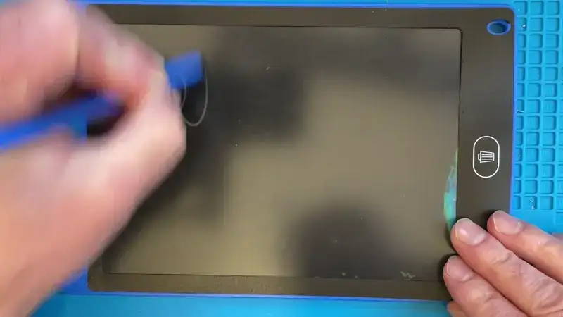
I designed a drop-in replacement board that generates 27V, which is enough to fully reset the bistable LCD. The fit isn’t perfect yet — the battery and PCB need a touch of case “surgery” — but functionally it’s solid.
How the Circuit Works
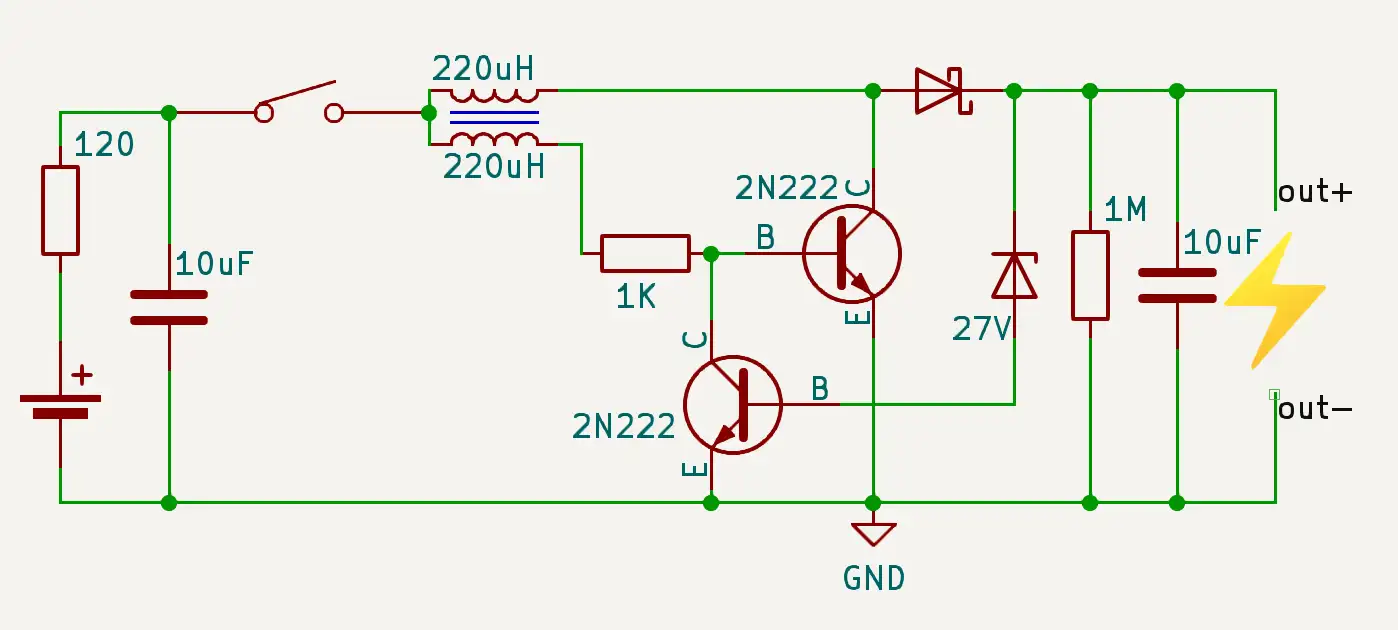
If you missed the earlier exploration, I used a simple Joule Thief circuit to step a coin cell up to ~27V. This version adds output regulation, so once we hit the target voltage it sips power.
BOM & Key Bits
Input side
- 120 Ω inrush limiter
- 10 µF input capacitor
- Tactile “blister” button (salvaged from the old board after a new one turned out slightly oversized)
Output side
- 10 µF output capacitor
- 1 MΩ bleed resistor
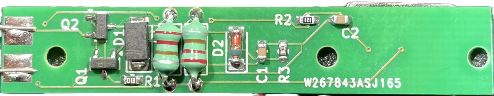
Boost core
- Two 220 µH inductors (magnetically coupled by proximity)
- Main switching transistor + feedback transistor
- 27 V Zener for regulation (pulls the main transistor base low when the target is reached)
⚠️ Crucial detail: the two inductors must be soldered in opposite orientations. Get this wrong and the oscillation won’t start.
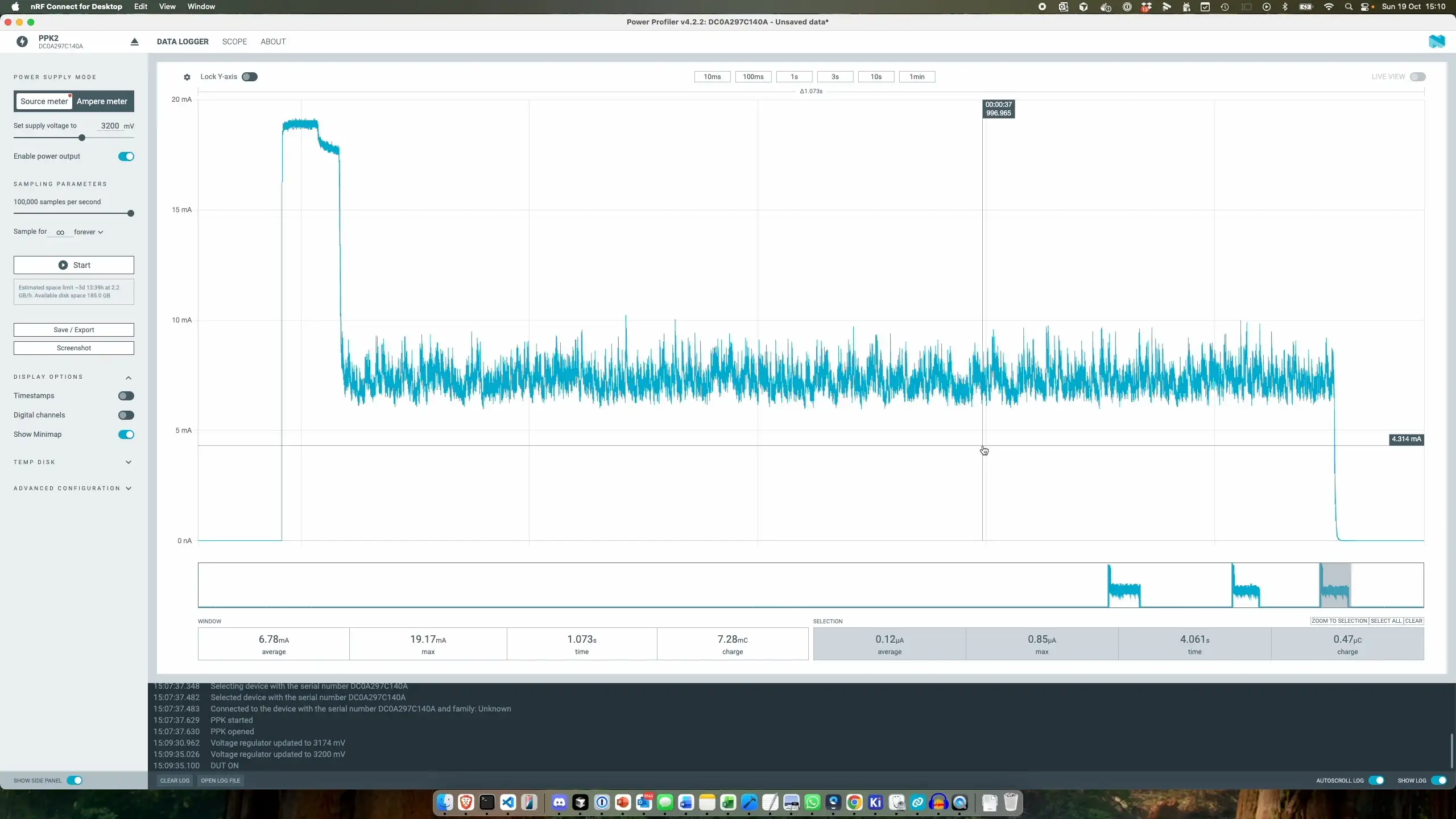
Power Profiling
I profiled the board using a Nordic Power Profiler. At 3.2 V input:
- Button press (charge-up):
- Peak current ≈ 19 mA
- Average during ramp ≈ 17 mA
- Regulating at 27 V:
- Average ≈ 7–7.6 mA (saw peaks ≈ 10 mA)
This is very reasonable for a coin cell, especially since the high current is short-lived during the charge pulse.
| Scenario | Peak (mA) | Avg (mA) | Notes |
|---|---|---|---|
| Charge-up | ~19 | ~17 | Initial button press |
| Regulating | ~10 | ~7.26 | At 27 V target reached |
All in all pretty neat - this will last for quite some time on the single coin cell. Just need to do a bit of work to make the repair a bit more seemless…