🌈 ESP32-S3 Rainbow: ZX Spectrum Emulator Board! Get it on Crowd Supply →
View All Posts
read
Want to keep up to date with the latest posts and videos? Subscribe to the newsletter
HELP SUPPORT MY WORK: If you're feeling flush then please stop by Patreon Or you can make a one off donation via ko-fi
#1-BIT AUDIO #CH32V003 #COIN CELL #EMBEDDED #GITHUB #LOW-POWER #MCU #MIDI #PCB #PIEZO BUZZER #POWER OPTIMIZATION #RISC-V #SOLDER PASTE #WCH #WLINK

These super cheap (around $0.10 in bulk) RISC-V MCUs from WCH have been pretty popular recently. I recently had a need for a small, low power MCU and my usual choice of an Espressif module would have just been too power hungry - and also too large.

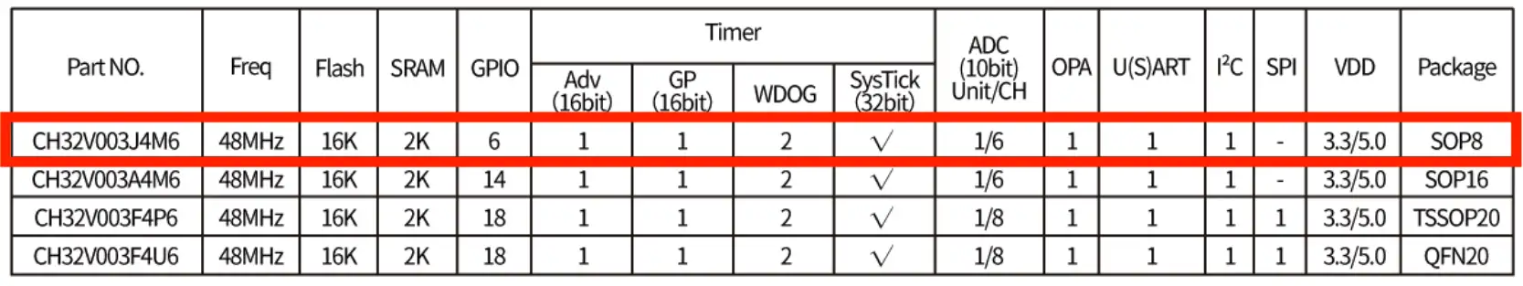
I’m using the smallest version of the CH32V003 - the CH32V003J4M6 - this is an 8 pin IC. It’s definitely a massive step down from what we normally have to play with. It’s got 16K of flash and only 2K of RAM. The CPU is pretty reasonable though - it’s RISC-V running at 48MHz - so not too shabby.

CH32V003J4M6 Specifications

There are a lot of online guides to programming this chip - so I’m not going to do a deep technical dive. Here’s a good starting point as is this seies.

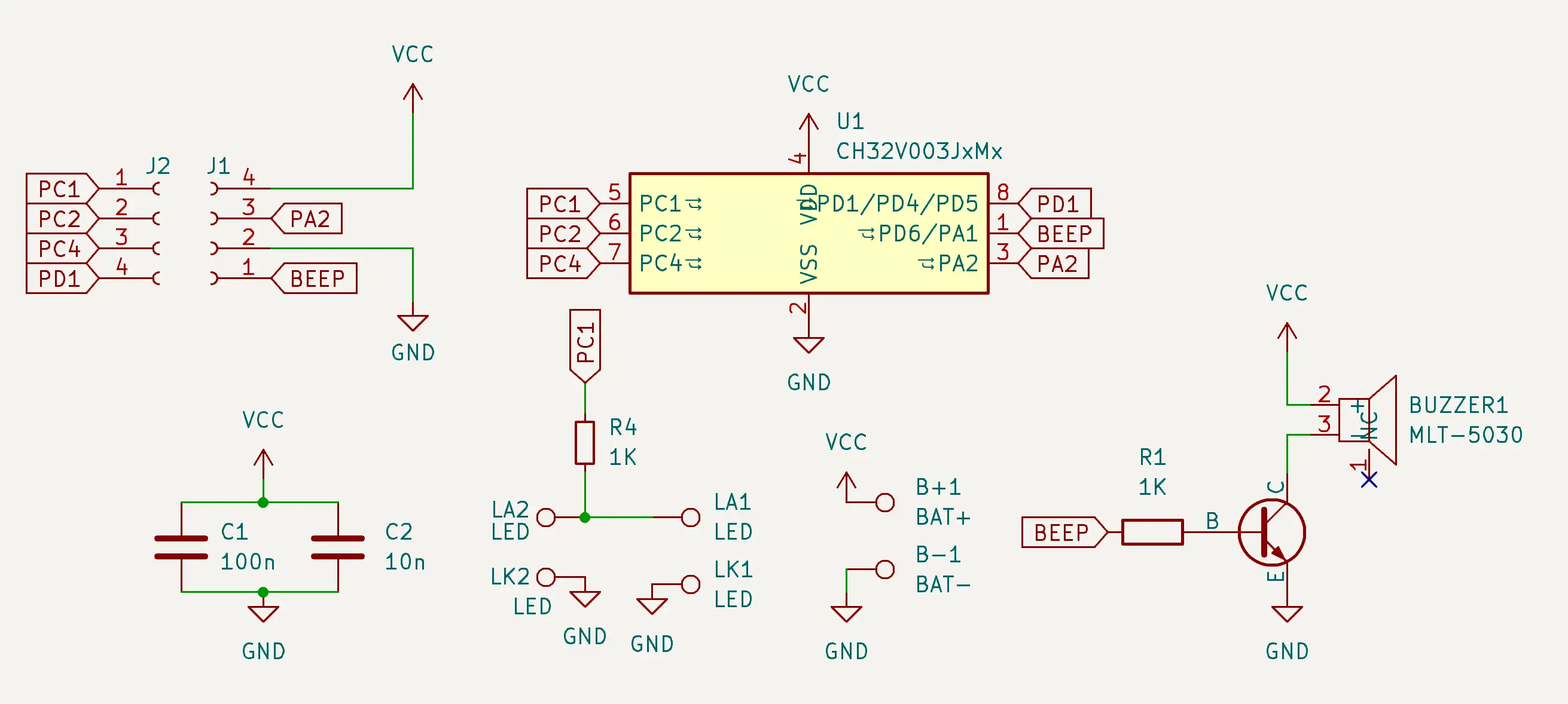
You don’t need very much to bring this chip up. It’s got its own built in voltage regulator - so you can feed it anything from 2.7~5.5V and it just needs a 100nF decoupling capacitor.

For our project, I took inspiration from this project - which is a coin cell powered mini game console. This was a good starting point as it included a buzzer. Here’s my schematic:

Schematic

And the final PCB layout:

PCB Layout

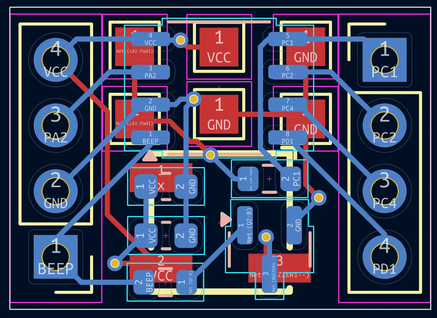
Despite me adding pin headers, we still ended up with a very small board: 16.3mm X 11.7mm.

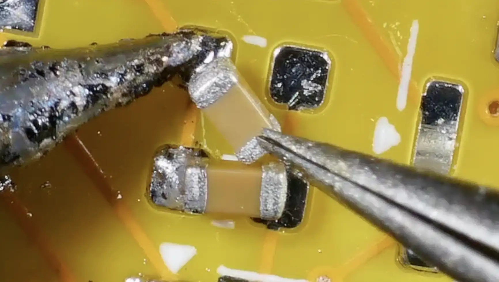
I got the boards made up by PCBWay. I skipped ordering a stencil as there are very few components on the board, so not too hard to solder up by hand.

Soldered Up

But I had forgotten how painful soldering under the microscope was.

Soldering

Then I remembered - I have a PCB printing machine that also dispenses solder paste!

Solder paste dispensing

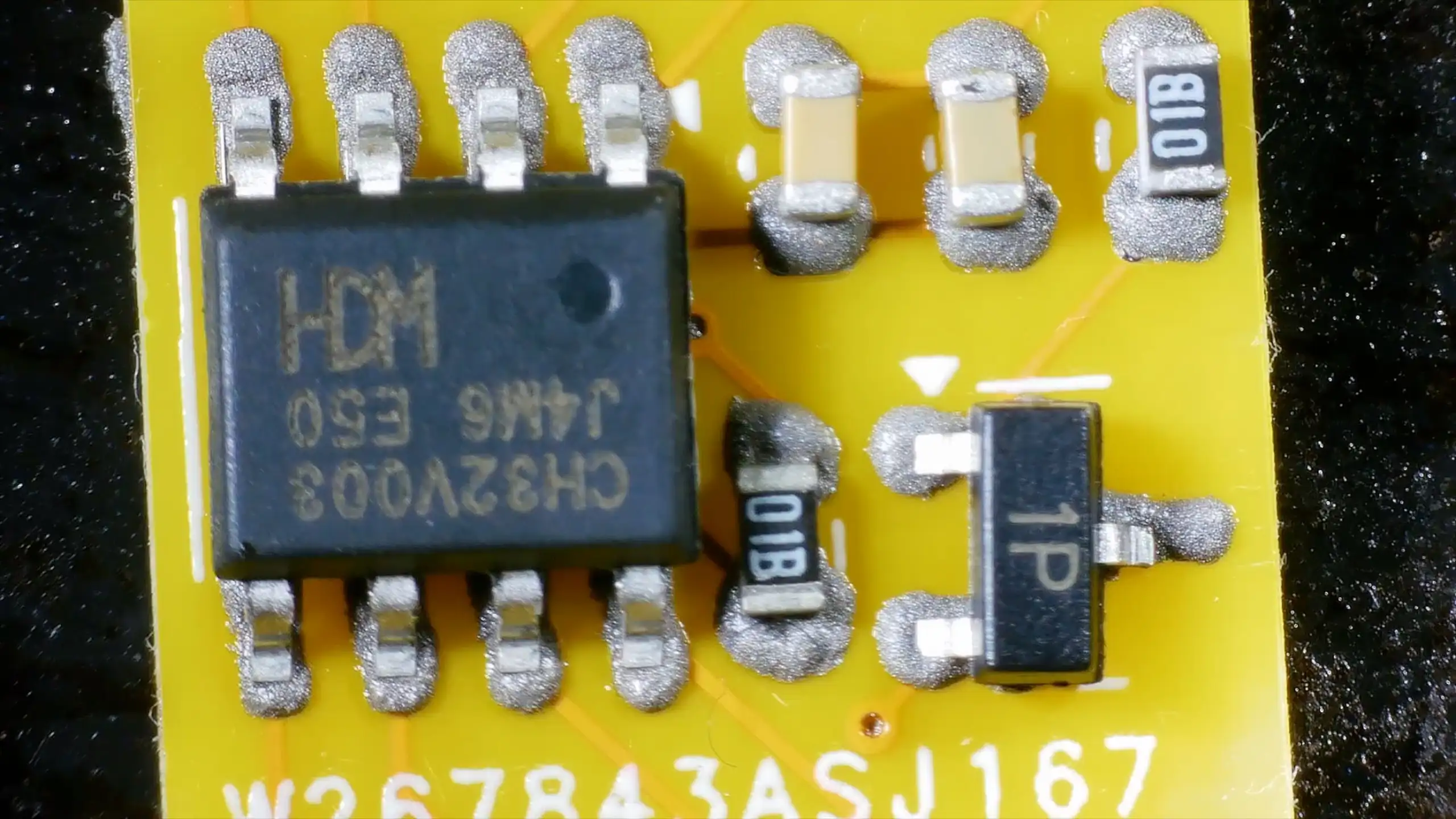
I was pretty amazed at how well this came out, especially considering the solder paste I used is almost three years past its best-before date!

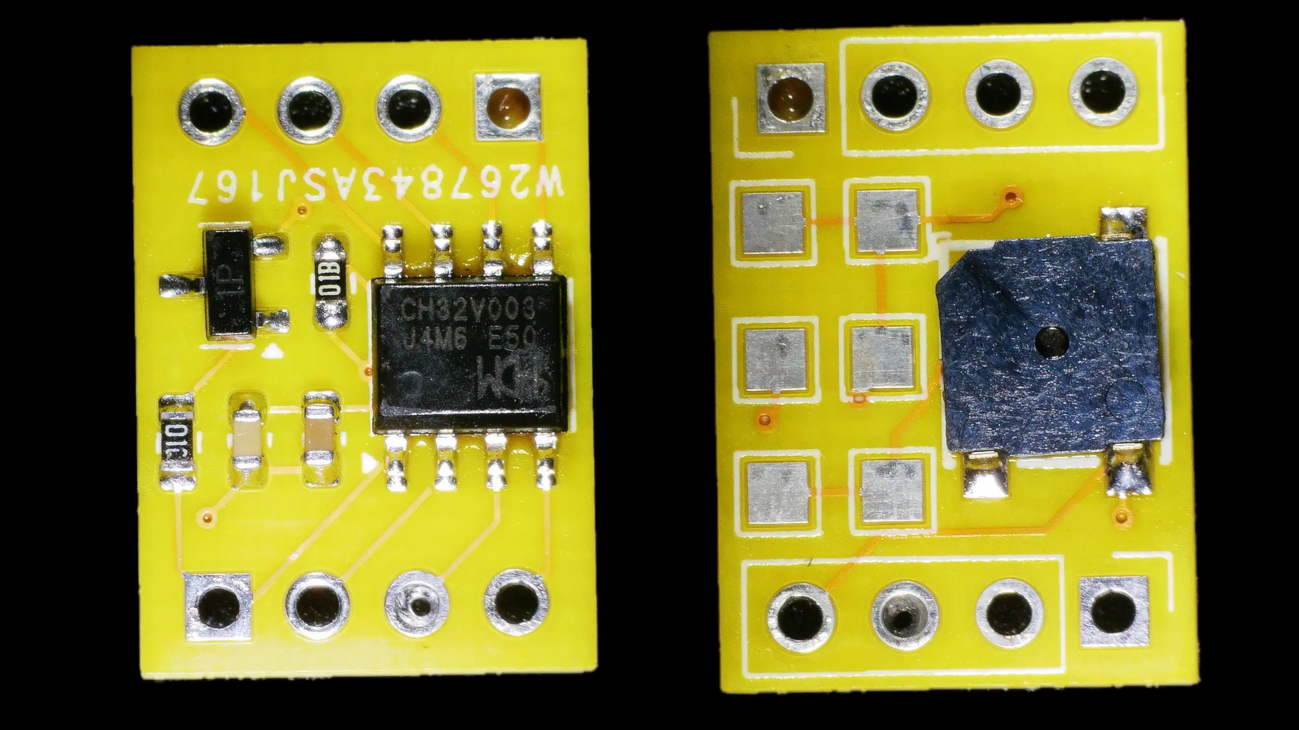
Each board consists of:

  • One CH32V003 MCU
  • A small piezo buzzer driven by a transistor

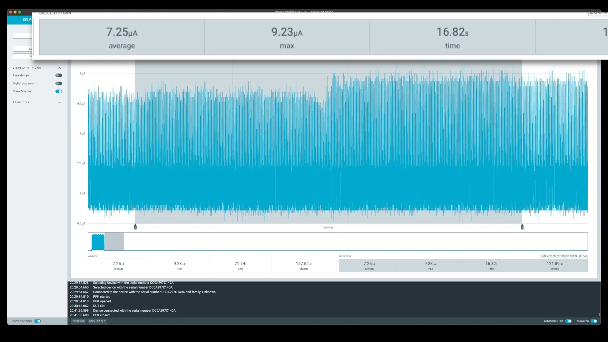
My plan is/was to power these boards from a CR2032 coin cell battery. In standby mode the power consumption is very good - around 7-8µA.

Standby Mode Current Draw

I did find a bit of a problem with standby mode - with the device in standby, I couldn’t program it anymore - which is a bit of a pain when you are trying to develop. And even worse if your wakeup is not working. For a while, I thought I’d bricked it completely.

Fortunately there is a way to get back to a good known state. The wlink utility can be used to erase the flash even in standby mode.

$ ./wlink erase --method power-off --chip CH32V003

When playing music, the power consumption is a different story. When the MCU is in active mode, it’s a very reasonable 3.3mA. But as soon as we start playing audio, we spike up to 130mA.

Current spike during playback

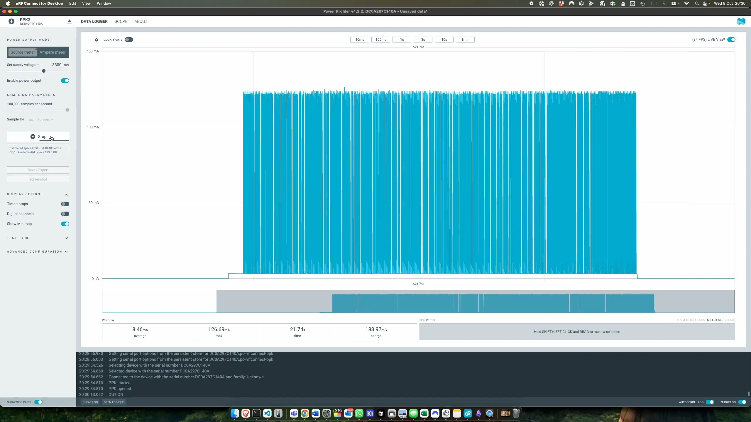
I am using a very low mark-space ratio on my audio output (the buzzer is only on for a small fraction of the time), so we do only average 13-14mA, but the 130mA peaks are too much for a coin cell - as soon as we play audio, the device browns out.

My backup plan was to use one of these tiny Lithium cells. I did have to modify one of my charger boards for this cell - I don’t think pumping 1A into an 80mAh cell would end well…

Tiny 80mAh lithium cell

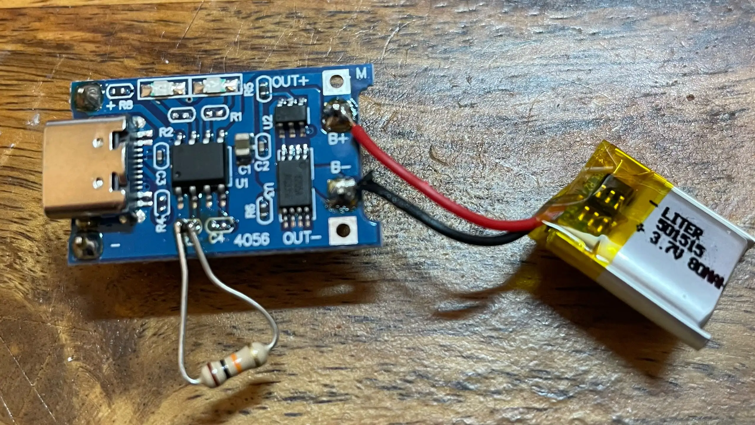
With the LiPo, we get more than enough juice to power the board and play the music without issues.

But I really wanted to get this working with a coin cell. I modified one of the boards to use a much higher base resistor on the transistor - bumping this up to 10K.

Tiny 80mAh lithium cell

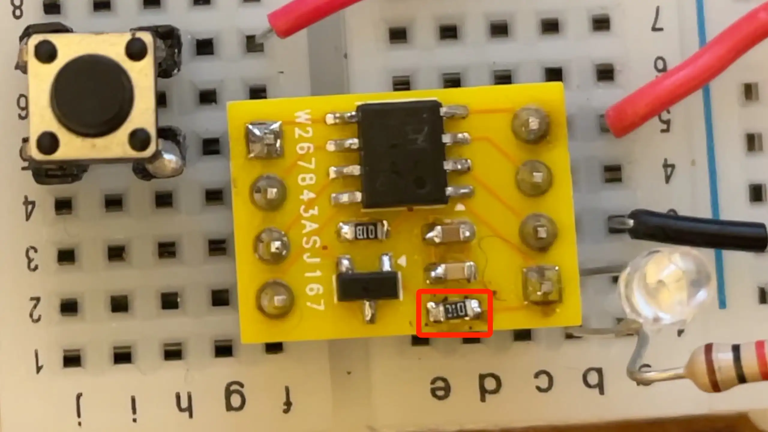
With this, we got some much more reasonable results.

  • Peak current: 56 milliamps (down from 130mA!)
  • Average current: Just over 7 milliamps (down from 13-14mA)

Much lower current requirements

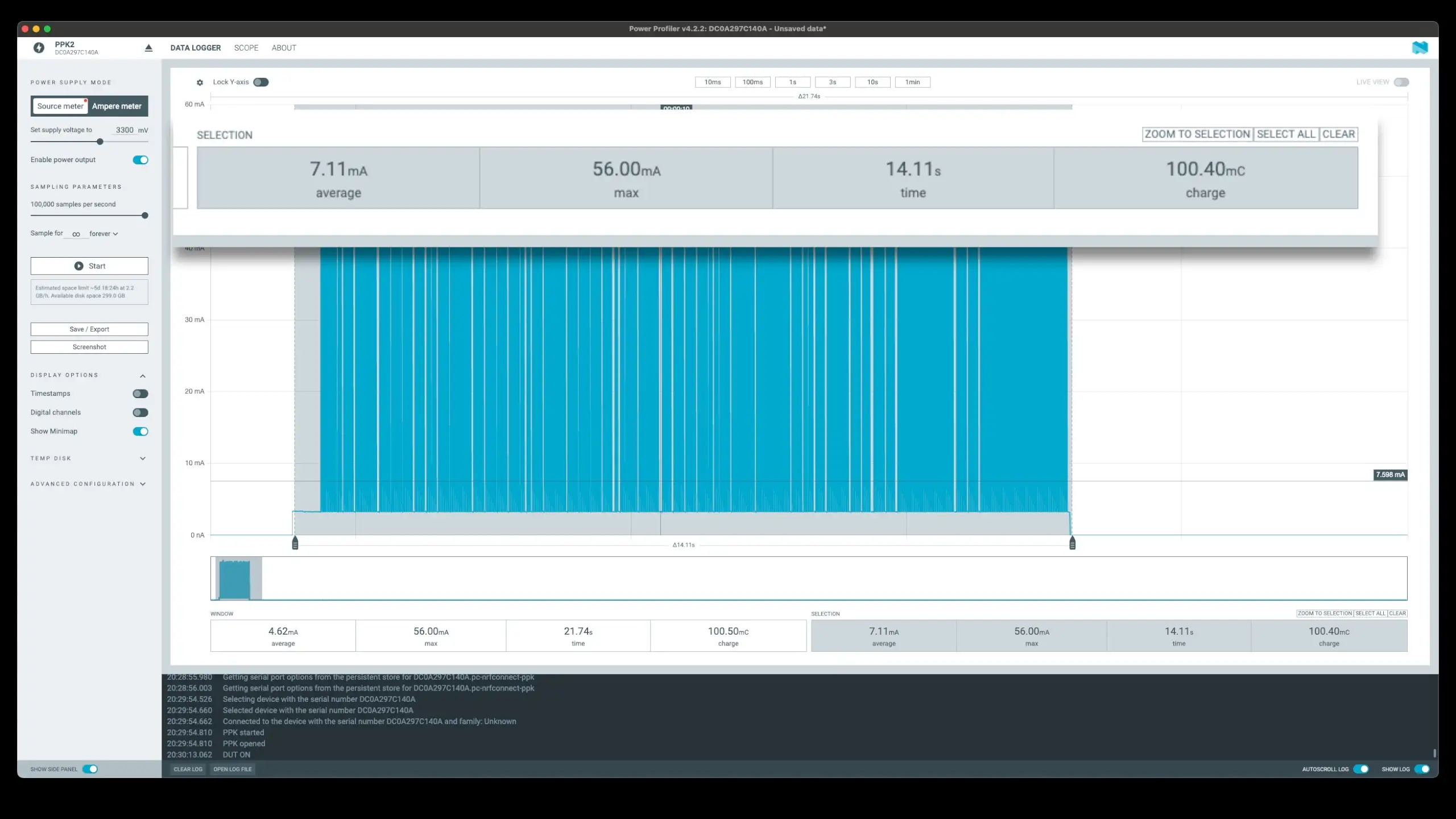
This version works beautifully with the coin cell, plays all the way through, and is still plenty loud enough for my purposes.

My actual code for playing back the audio is very simple and naive. I’m just bit-banging the GPIO pin with the note frequency.

It doesn’t sound too bad for one of these tiny buzzers - it’s actually pretty impressive!

To actually get the audio data I put together a simple tool (well, my AI chum put it together…). This lets you export a track from a midi file in a simple format that the MCU can use.

MIDI file conversion diagram

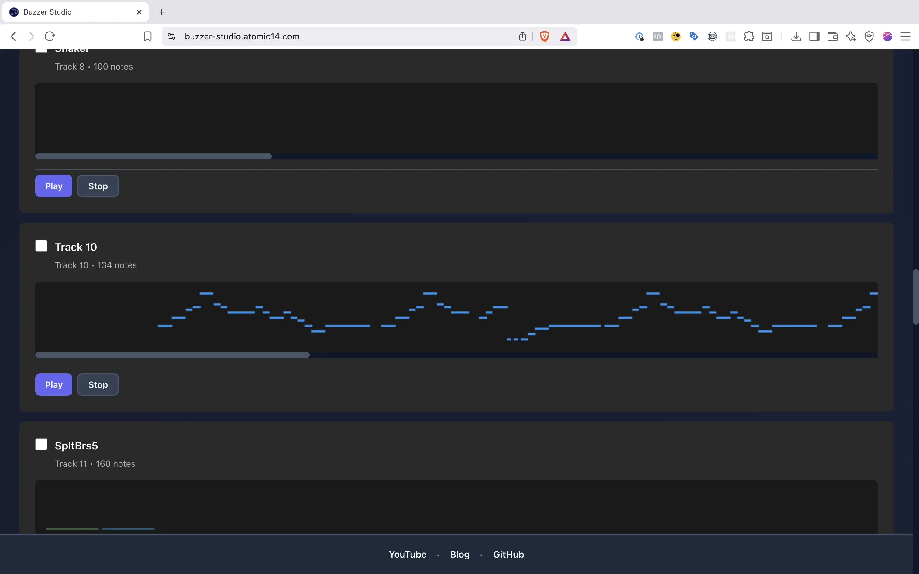
This also contains a very simple 1-bit Sound FX generator which is quite fun.

All the code for the project is on GitHub.

And you can listen to the results here:

#1-BIT AUDIO #CH32V003 #COIN CELL #EMBEDDED #GITHUB #LOW-POWER #MCU #MIDI #PCB #PIEZO BUZZER #POWER OPTIMIZATION #RISC-V #SOLDER PASTE #WCH #WLINK

Related Posts

High voltage coin cell - I blew up the original PCB on a bistable cholesteric display, so I built a coin-cell Joule thief to crank out 27V and bring it back to life. A simple two-inductor setup with a 27V Zener does the trick—about 10 mA while the button’s held. Then I got fancy with a regulated version (just one extra transistor) that tops the cap to 27V and basically idles—average draw lands around 1.53 mA. It’s neat, tiny, and perfect for this low-current reset job. Full build and measurements are in the video.
Worlds smallest USB-C Li-Ion charger - I stumbled upon these incredibly tiny USB-C Li-ion chargers on AliExpress and couldn't resist checking them out! These minuscule PCBs, just 10mm x 6mm, feature the LP4054 (or TP4054) linear battery charger. With a 1.65K programming resistor, they offer a charging current of around 600mA. Keep in mind, they can get pretty toasty, reaching up to 92-93C! For fun, I tried recreating them in KiCad and found it surprisingly easy.
Minimalist Microcontroller: Building a Bare-Bones Dev Board - In a thrilling DIY endeavour, I attempted to build the most minimalist ESP32 dev board possible. Diving deep into the schematic of the ESP32 S3 WROOM module, I chopped out the non-essentials and whittled our needs down to bare bones. The experiment saw me juggling USB data lines and voltage regulators, waving goodbye to an array of capacitors and connectors and boldly embracing the simplicity of direct connections. Despite a few hitches, the miniature Frankenboard came alive, proving that sometimes less is more...at least in the world of microcontrollers.
Tearing Down a Bistable Cholesteric Display - I recently dug out my bistable cholesteric display and decided to see how it works after being inspired by Big Clive's teardown. This nifty gadget, which allows you to write and erase with just a button, operates on bistable cholesteric crystals without needing constant power. Measuring the clear voltage showed around 30V, and a little experimentation confirmed its dependency on polarity. Despite a minor spark mishap, it's still a neat, low-power device. If you're interested, you can grab one from AliExpress for some hands-on fun.
Red Arcade Thing Repair - I resurrected a dead AliExpress arcade handheld by swapping the blown 3.3V regulator (I now own 99 spares), adding a TP4056 charger with Schottky diode isolation, and nursing a 0V LiPo back to life. A bit of hot-plate rework, tidier wiring, and—flip the switch—boom: it boots! It’s not pretty, but it’s alive again.

Related Videos

Turning a 10¢ MCU Into a Music Machine - CH32V003 - I spun some tiny WCH boards at PCBWay around an 8‑pin MCU (48 MHz, 16k flash, 2k RAM) to beep tunes off a coin cell. I tried hand-soldering, then used my paste-dispensing PCB printer—expired paste still worked great. Standby sips under 8 µA, but it locks out programming; a WLink flash wipe rescued me. Wake draws ~3.3 mA, and audio peaks hit ~130 mA (~13–14 mA average), which browned out the coin cell. A tiny 80 mAh LiPo with a TP4056 (modded to ~100 mA) proved the design, then swapping the buzzer’s base resistor from 1k to 10k tamed it to ~56 mA peak and just over 7 mA average—coin cell friendly and still loud. I’m bit-banging audio for now (PWM/timers later). I also made a quick MIDI-to-note tool and a one-bit SFX generator. These boards are heading into my next project—stay tuned.
High Voltage Coin Cell - 27V Joule Thief - How much voltage can we squeeze out of a CR2025? Turns out… plenty! I built a little Joule-thief-style boost circuit with two 1 mH inductors, an NPN, a Schottky, a 27 V zener clamp, and a storage cap to zap my LCD pad clean at around 27 V. I profiled it with a Nordic power monitor: about 11 mA during the boost and ~9.28 mC per click—so tens of thousands of presses from one coin cell. Then I added a second transistor tied to the zener to auto-limit the drive, dropping hold current to about 1.5 mA—huge win. Scoped it (~38.7 kHz, base swinging to nearly -6 V), laid out a PCB, 1:1 print check for fit, and sent the gerbers off to PCBWay.
Dodgy circuit could have caused a fire! - So, I got this red mini handheld game thing from AliExpress and it died pretty quickly. After a bit of tinkering, I found that it still draws current but isn't turning on because of a dead battery and a burnt voltage regulator. I removed the faulty components and injected 3.3 volts directly into the system, and guess what? The screen lights up and it works, but there's no sound. Despite the hiccup with my microscope, which stopped recording some interesting bits, you get the picture. It's partly revived but not quite there yet. Big shout out to PCB way who help us out with PCBs!
ESP32-S3 USB UAC Audio Device - does it work? - Time for an audio project: I took my PCBWay ESP32‑S3 board for a spin—fixed the common anode/cathode LED mix‑up, verified the IMU and battery charger, then tested an I2S PDM mic and tiny speaker with a Web Serial Audio Studio (scope, spectrogram, tuner). I also turned it into a USB UAC device in ESP‑IDF: the mic is clean, but speaker over UAC is crackly (Mac/Windows toggle oddity); direct I2S WAV playback is perfect, so the hardware passes QA.
Another Street Battery Salvage - In this video, I plucked a battery from a Honey Melon street crystal, ending up with another 500-milliamp hour battery to add to my growing collection. After checking the connection, I added a protective PCB and tested the battery - a reasonable 3.5 volts at a flat level. Following the safe soldering of wires and wrapping it up, I hooked the revamped battery to my charger. It showed promising results, charging quickly at one amp with voltage visibly on rise. After a full recharge, I performed a load test which unfortunately gave a disappointing 311 milliamp hour. It falls short of my other salvaged batteries – 500 and 550 milliamp hour, but nonetheless, it’s a fine addition to the collection.
HELP SUPPORT MY WORK: If you're feeling flush then please stop by Patreon Or you can make a one off donation via ko-fi
Want to keep up to date with the latest posts and videos? Subscribe to the newsletter
Blog Logo

Chris Greening


Published

> Image

atomic14

A collection of slightly mad projects, instructive/educational videos, and generally interesting stuff. Building projects around the Arduino and ESP32 platforms - we'll be exploring AI, Computer Vision, Audio, 3D Printing - it may get a bit eclectic...

View All Posts