Building a Heart Rate Monitor with an ESP32-C3 and MAX30102
You know how it is. You buy one cute little module from AliExpress and then think “it looks lonely, I’ll get another”. Before you know it, you’ve got a drawer full of cute little modules. So it’s time to put one of them to work.
The ESP32-C3 Board
I’ve got a bunch of these tiny ESP32-C3 boards kicking around. Let’s take a look at one under the microscope.
The brains of the operation is an ESP32-C3 with built-in flash — four megabytes of it, which is pretty decent.
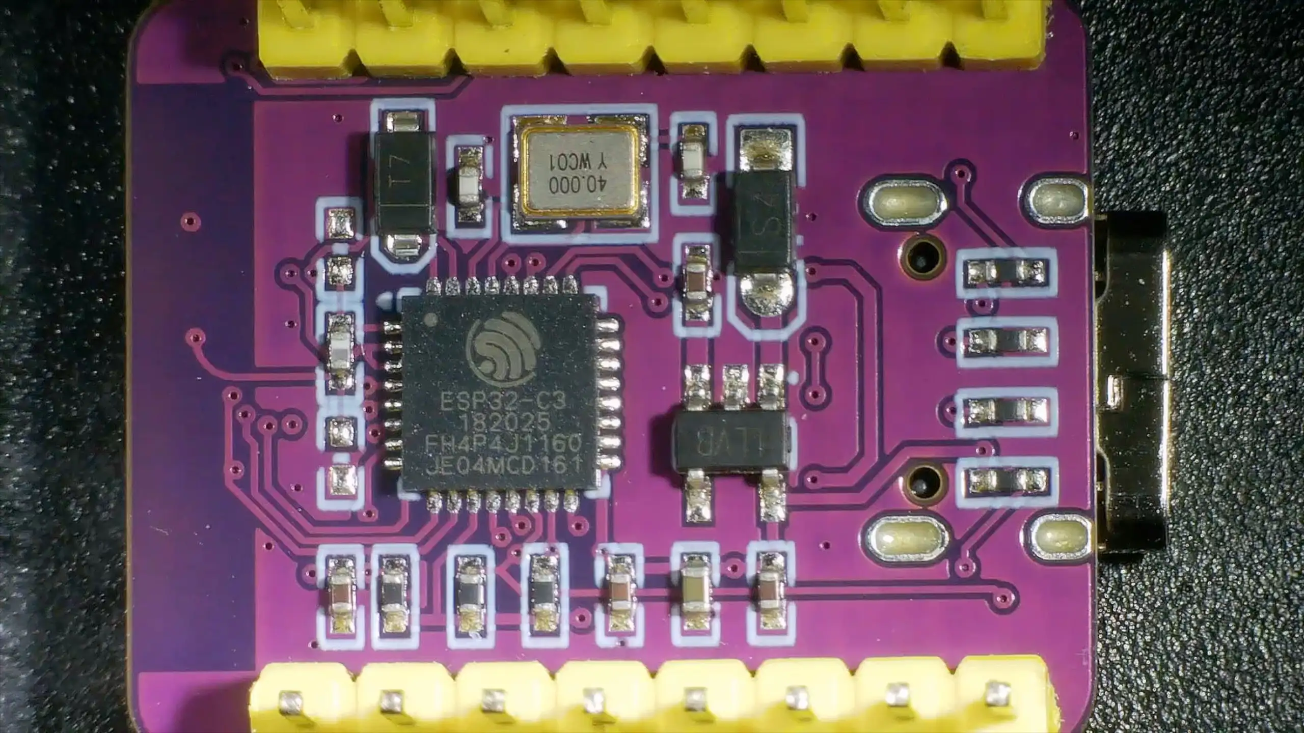
There’s a 3.3 volt regulator on board, and the soldering looks nicely done. It’s a pretty clean, well-designed little board. The antenna is a ceramic one on the side — though I’ve read a few people saying that on these tiny compact boards you don’t get much Wi-Fi signal due to the antenna placement being a bit too close to the buttons and other components. So we’ll avoid Wi-Fi for this project.
The MAX30102 Heart Rate and Blood Oxygen Sensor
For the actual sensor, I’m using a MAX30102 module — a heart rate and blood oxygen monitoring board that I picked up in a recent AliExpress order.
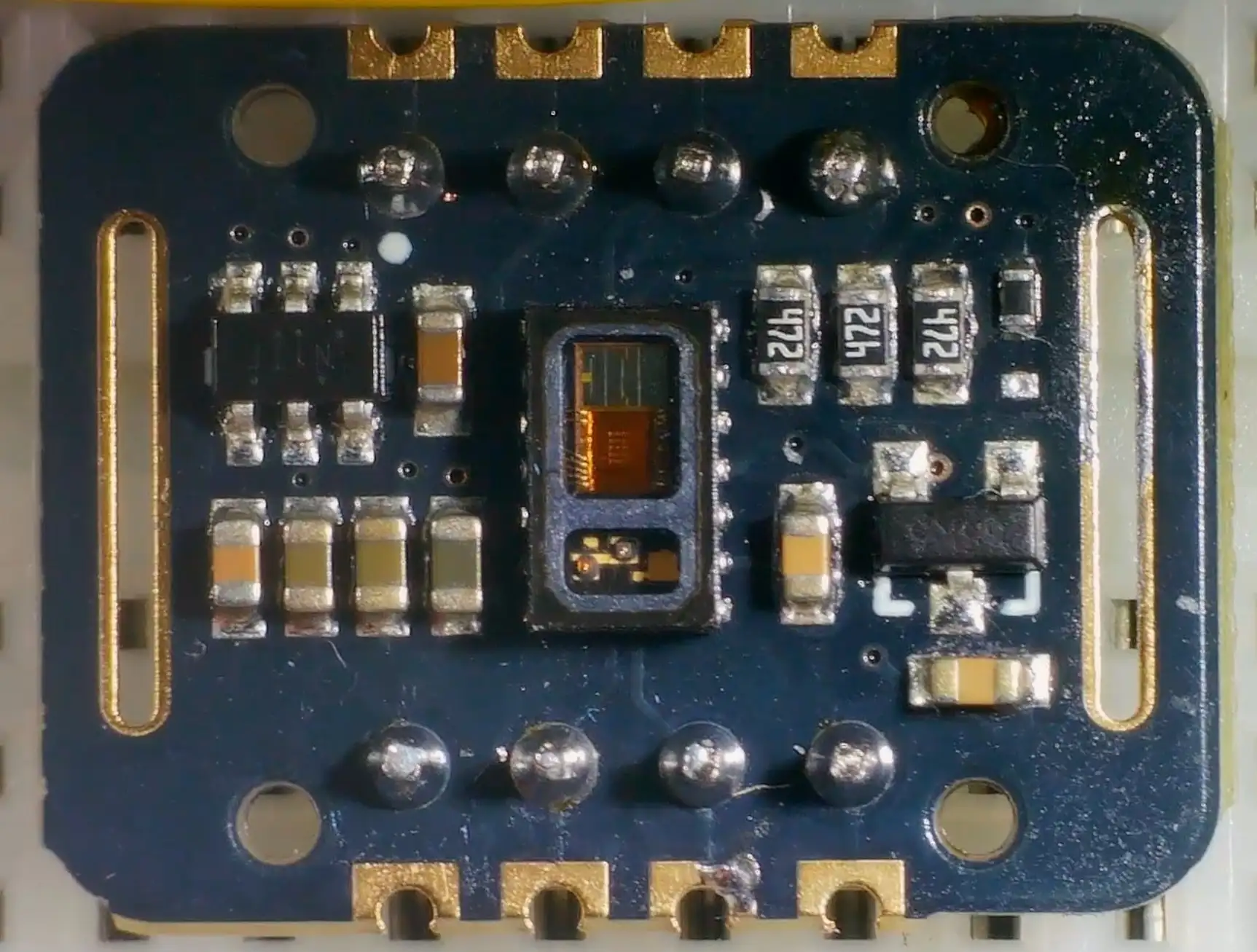
The board has a 3.3 volt boost regulator and a 1.8 volt regulator. Some people have reported finding a 2.8 volt regulator instead of 1.8 on some boards — it’s worth checking yours is correct. Mine was fine.
How the Sensor Works
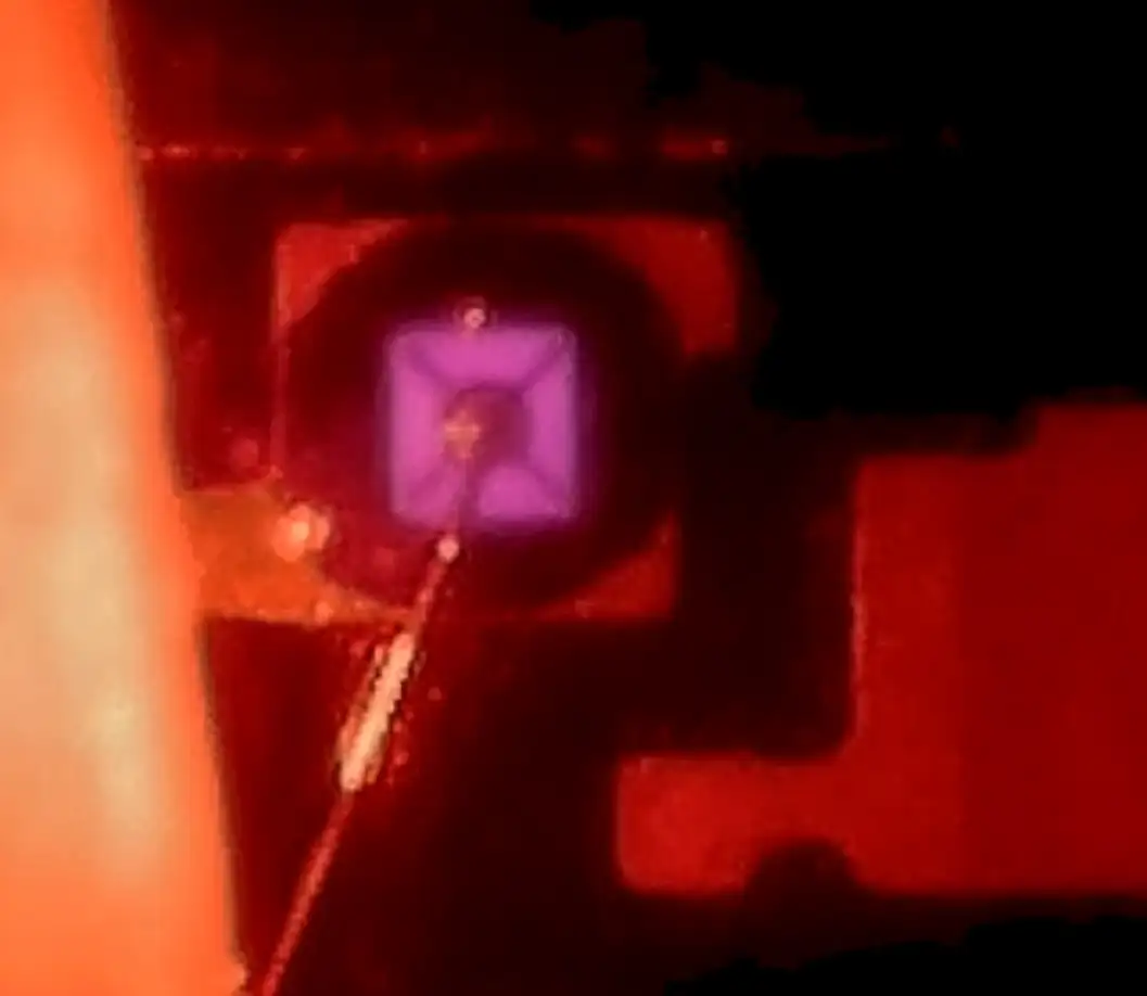
The really interesting part is the sensor itself. Under the microscope you can see:
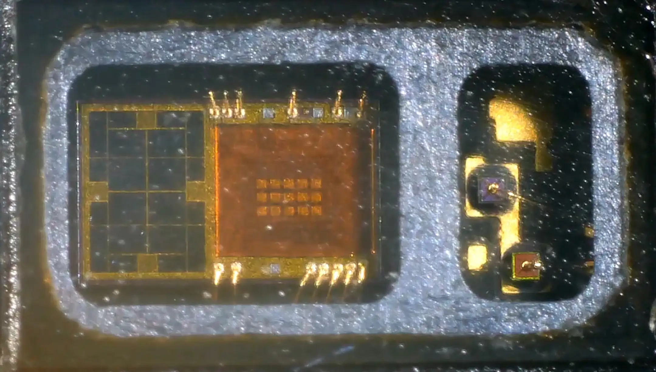
- Two LEDs behind a window — a red LED and an infrared LED
- A photodetector with a bunch of DSP processing built in
The outputs from this device are just the value of the red channel and the value of the infrared channel. You stick your finger on top and it detects pulse rate using the red LED and blood oxygen levels using the infrared LED.
When you power it up, you can easily see the red LED. If you cover it up and move the lights away, you can even see a slight glow from the infrared LED — the camera on the microscope picks it up nicely.

Wiring It Up
The wiring is pretty simple — it’s just I2C plus power:
const byte oxiInt = 2; // pin connected to MAX30102 INT
const int SENSOR_I2C_SDA_PIN = 5;
const int SENSOR_I2C_SCL_PIN = 6;
- Pin 6 → SCL
- Pin 5 → SDA
- Pin 2 → Interrupt (tells us when data is ready)
- 5V → Vin (the board has its own 3.3V regulator)
- GND → GND
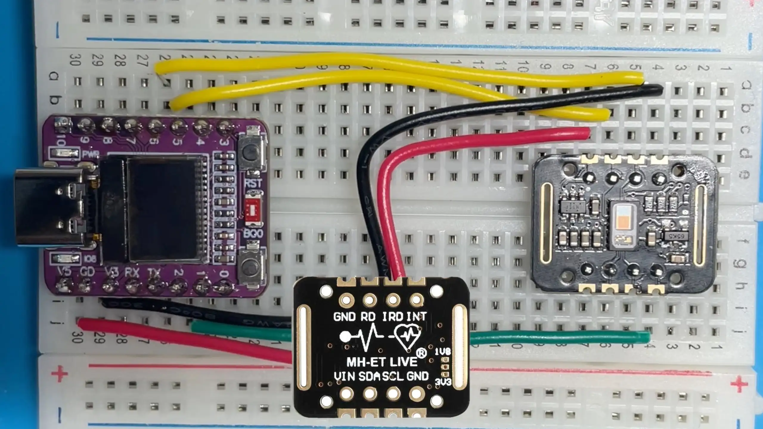
A quick I2C scan confirms everything is connected properly — two devices show up: the I2C display and the heart rate monitor.
The Code
The main loop reads samples from the MAX30102 into a ring buffer, then runs the heart rate and SpO2 algorithms once the buffer is full:
void loop() {
  float n_spo2, ratio, correl;
  int8_t ch_spo2_valid;
  int32_t n_heart_rate;
  int8_t ch_hr_valid;

  // Read UPDATE_STEP new samples into the ring buffer
  for(int32_t n = 0; n < UPDATE_STEP; ++n) {
    readNextSampleIntoRing(data_ready_timeout_us);
  }

  // Need a full buffer before we can calculate
  if(sample_count < BUFFER_SIZE) return;
  buildOrderedWindow();

  // Calculate heart rate and SpO2
  rf_heart_rate_and_oxygen_saturation(
    ordered_ir_buffer, BUFFER_SIZE, ordered_red_buffer,
    &n_spo2, &ch_spo2_valid,
    &n_heart_rate, &ch_hr_valid,
    &ratio, &correl);

  // Median filter smooths out noisy readings
  hr_filter.push(ch_hr_valid ? n_heart_rate : INVALID_HR);
  spo2_filter.push(ch_spo2_valid ? n_spo2 : INVALID_SPO2);

  updateDisplay(filtered_heart_rate, (int32_t)filtered_spo2);
}
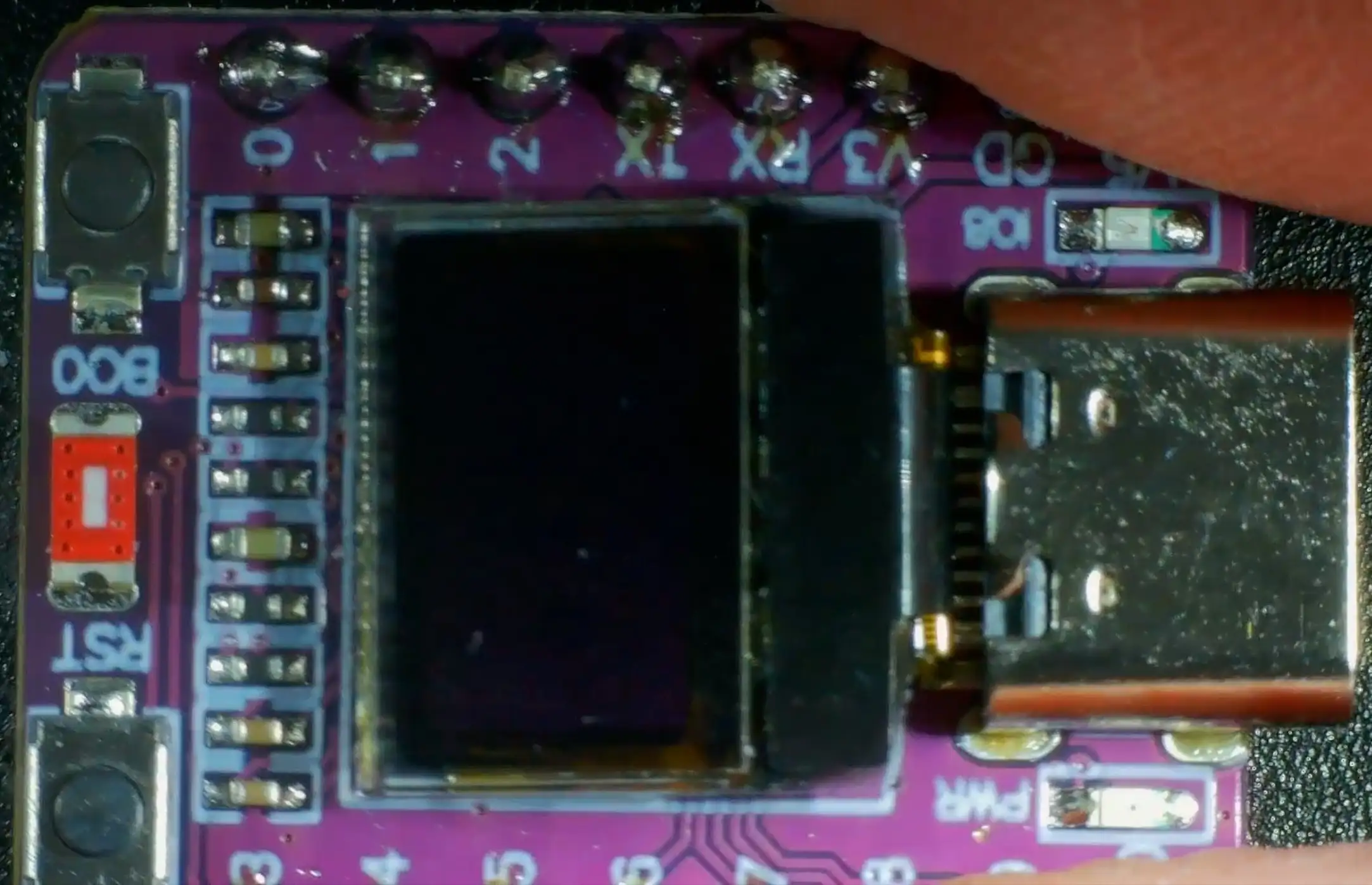
The display code is pretty straightforward — just show the heart rate and oxygen percentage on the tiny OLED, or dashes if we don’t have a valid reading:
static void updateDisplay(int32_t hr, int32_t spo2) {
  u8g2.clearBuffer();
  u8g2.setFont(u8g2_font_10x20_mr);
  u8g2.setCursor(0, 19);
  if (hr >= 30 && hr <= 250) {
    u8g2.printf("HR: %d", (int)hr);
  } else {
    u8g2.print("HR: --");
  }
  u8g2.setCursor(0, 39);
  if (spo2 >= 0 && spo2 <= 100) {
    u8g2.printf("O2: %d%%", (int)spo2);
  } else {
    u8g2.print("O2: --");
  }
  u8g2.sendBuffer();
}
There’s also a nice touch — the on-board LED flashes in time with your heartbeat.
Getting Readings
With the sketch uploaded and the OLED display showing results, it’s time to test.
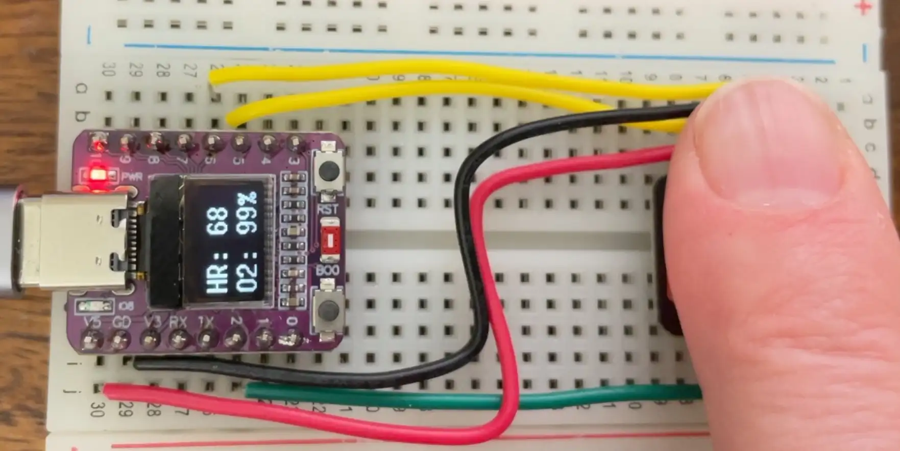
It can be a bit finicky about finger placement — you need to keep it very still. But once it settles, it starts producing results: heart rate and SpO2 percentage.
Comparing to a Commercial Device
The real test — how does it compare to a proper pulse oximeter?
With both running side by side:
- Heart rate: around 70 BPM on the ESP32-C3, matching the commercial monitor
- Blood oxygen: 99% on both devices
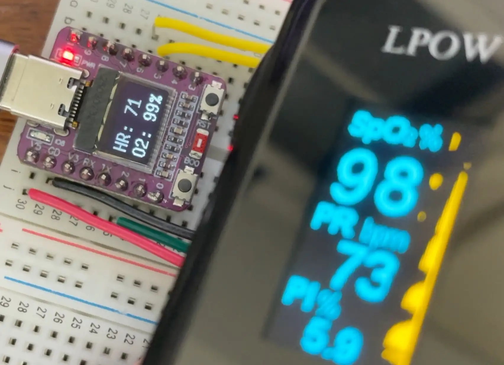
Not bad at all. The main challenge is keeping your finger positioned accurately without squishing it on — it’s quite easy to lose the reading. But when you get a good contact, the results match up well.
Wrapping Up
The full code is on GitHub. Grab yourself one of these ESP32-C3 modules, a MAX30102 sensor, and a little OLED display, and you can build something equivalent to a commercial pulse oximeter for very little money. It’s a fun project — why not try it out?